mohan-bee/fitness-band
A 4-layer BLE wearable mainboard with Li-ion charging/protection, 3.3/1.8 V power regulation, motion and battery sensing, plus a folded 2-layer flex sensor board carrying MAX30102 optical and TMP117 temperature sensors.
- Version
- 0.0.2
- License
- unset
- Stars
- 0
HARDWARE_REVIEW.md
# Hardware review — prototype revision B

This is a bench-prototype fabrication release, not a production wearable qualification. Acceptance evidence is in manufacturing/rev-b/release-manifest.json and validation/*-native-drc.json. Platform failures belong only in ISSUES.md.

## Corrections implemented

| Area | Final design |
| --- | --- |
| Radio geometry | Raytac Rev L land pattern/normal-voltage circuit checked. U1 at (−18.7, 0), rotated 90°. Antenna x −28.2…−24.4; host left edge −25; overhang 3.2 mm. |
| RF copper | All-layer antenna reserve across the board height. Separate top-only notch x −24.4…−23.2, y −2.3…−0.7. Native keepouts retained; In1 GND plane starts at x −24.2. |
| Module supply | VDD and VDDH tied to regulated 3.3 V in normal-voltage mode; VBUS NC. Use module-internal Reg1 components and firmware matching the fitted clocks. |
| Charger | BQ25180 replaced by standalone MCP73871T-2CCI/ML because the former's reset temperature profile was unsuitable for relying on firmware-independent 45°C protection. |
| Charge settings | R7 20 kΩ: 50 mA nominal; R8 100 kΩ: 10 mA termination. Part suffix 2CC supplies 4.2 V and the 6-hour timer. TE/PROG2 low; SEL/CE high from input; VPCC tied to input as documented. |
| Battery | Protected PKCELL LP402025 150 mAh pack, as documented for Adafruit 1317. Standard charge 30 mA; specified maximum 150 mA. The selected 50 mA is below that maximum. Do not substitute an unreviewed 100 mAh cell. |
| Cell NTC | Semitec 103NT-4-R025H41G attached electrically insulated to the pouch; R9 162 kΩ shunt. TMP117 skin temperature is not a cell-temperature sensor. Open/short NTC faults inhibit charging. |
| Dock protection | 1206L020YR fuse, PMEG2010ER-QX reverse-polarity Schottky, PESD5V0S1BA-Q TVS, local input capacitor. |
| Charger bypass | C3 input, C4 battery, C5 SYS: 10 µF/25 V 0805 X5R, providing derating margin over small nominal 4.7 µF parts. |
| Buck-boost | TPS63031: FB to output, PS/SYNC low, EN/VINA to SYS. Local VIN 10 µF, VINA 100 nF, output 2 × 10 µF. Manual switch, feedback, output and PGND/EP routes. |
| Inductor | LPS3015-222MRC, 2.2 µH, 2.0 A Isat at 10% drop, 1.4 A Irms at 40°C rise. MRB imported land pattern retained; MRC is the current ordering suffix. |
| Ground/vias | Continuous In1 GND, local ground vias. Through vias 0.45/0.20 mm, annulus 0.125 mm. Duplicate vias removed; two overlapping flex pairs replaced by surface links and one retained hole each. |
| Trace process | Main default 0.15 mm, switch paths 0.30 mm; fine-pitch neckdowns about 0.112 mm. Declared main minimum 0.10 mm width/clearance. Flex minimum 0.15 mm trace width and pad-to-trace clearance. |
| PPG | MAX30102 pin 11 on 1.8 V, pins 9/10 on 3.3 V, pins 4/12 GND; 1/5/6/7/8/14 NC. Corrected imported misleading pin-5/6 labels. Local core/LED decoupling included. |
| Bus | 3.3 V pullups; MAX30102 digital pin tolerance checked separately from its 1.8 V core. Start at 100 kHz and measure harness rise time. |
| Other sensors | BMA400 CSB high/SDO low; TMP117 ADD0/EP grounded; MAX17048 VDD/CELL on protected battery, CTG/QSTRT/EP grounded. |
| Interconnect | Numbered eight-wire harness including three ground conductors; no unverified ZIF footprint or face-to-face mirror assumption. |
| Flex mechanics | Two separate boards. Straight 0.30 mm top bend traces, no bottom copper in the 10 mm bend reserve; R3 static fold. Bottom stiffeners: PI 0.15 mm tail and two FR4 0.4 mm supports. |
| Assembly artwork | Separate laser-coverlay/stiffener artwork. Coverlay windows merged where a web would be below 0.5 mm. Hand-solder contacts have no stencil paste. Charger EP: four 1.1 mm paste windows, 61.7% coverage. |

## Charging temperature calculation

MCP73871 THERM bias: 47–53 µA. Cold threshold: 1.20–1.26 V; hot: 0.23–0.27 V. Nominal pin resistances are 24.8 kΩ cold and 5.0 kΩ hot. With the 4126 K NTC and 162 kΩ shunt, nominal cutoffs are approximately 3–4°C and 40°C.

Using Semitec's R/T data and resistance/B tolerances gives design estimates of approximately 27.3 kΩ minimum at 0°C and 4.30 kΩ maximum at 45°C, after shunting. Compare with the most permissive thresholds: 1.26 V / 47 µA = 26.81 kΩ cold and 0.23 V / 53 µA = 4.34 kΩ hot. The electrical calculation places the allowed window inside the cell's 0–45°C range. Hot-side margin is small; actual thresholds, thermal lag and cell attachment must be measured. Initial charging is restricted to supervised room-temperature bench use until this test passes.

## Qualification after assembly

RF performance on a body, enclosure fit, optical quality, skin-temperature calibration, cell thermal tracking, current consumption and sweat resistance require physical testing. These are prototype acceptance tests, not tscircuit defects. Battery life is unmeasured; 150 mAh / 2 mA is only a theoretical 75-hour example.

Reserve the battery on the reverse at x −4…24, y −10.5…10.5, with an insulating spacer and no swelling pressure. Keep battery foil, flex copper, magnets and skin-contact metal out of the antenna zone. Support the module overhang in a nonmetallic housing. The optical sensor needs a light-blocking gasket/window, not bare skin contact with energized pads.

## Source references

- [Raytac documentation](https://www.raytac.com/product/ins.php?index_id=24); [manufacturer-authored Rev L specification, mirror](https://www.tme.eu/Document/ca89adf7c649a664a86d3b9f353f04d5/MDBT50Q-1MV2-INS.pdf): pp. 9–12 and normal-voltage circuit p. 40.
- [Microchip MCP73871 DS20002090F](https://ww1.microchip.com/downloads/aemDocuments/documents/APID/ProductDocuments/DataSheets/MCP73871-Data-Sheet-DS20002090F.pdf): electrical limits, pin table, temperature network, capacitance, C04-2126-ML land pattern.
- [Semitec NT-4 specification/R-T table](https://www.semitec-global.com/uploads/2022/01/P18-NT-Thermistor.pdf); [protected 150 mAh cell specification](https://cdn-shop.adafruit.com/product-files/1317/C1515_-_Li-Polymer_402025_150mAh_3.7V_with_PCM.pdf).
- [TPS63031](https://www.ti.com/lit/ds/symlink/tps63031.pdf), [TLV700](https://www.ti.com/lit/ds/symlink/tlv700.pdf), [TMP117](https://www.ti.com/lit/ds/symlink/tmp117.pdf).
- [MAX30102](https://www.analog.com/media/en/technical-documentation/data-sheets/max30102.pdf), [MAX17048](https://www.analog.com/media/en/technical-documentation/data-sheets/MAX17048-MAX17049.pdf), [BMA400](https://www.bosch-sensortec.com/media/boschsensortec/downloads/datasheets/bst-bma400-ds000.pdf).
- [Coilcraft LPS3015](https://www.coilcraft.com/en-us/products/power/shielded-inductors/ferrite-drum/lps/lps3015/); [JLCPCB flex capabilities](https://jlcpcb.com/capabilities/flex-pcb-capabilities).

Manufacturer documents were examined during this revision; URLs are provided rather than redistributing entire datasheets.
Related Packages
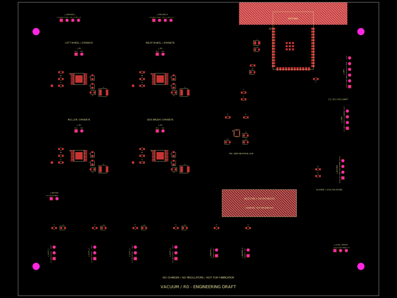 More from this authormohan-bee/tscircuit-robot-vacuum
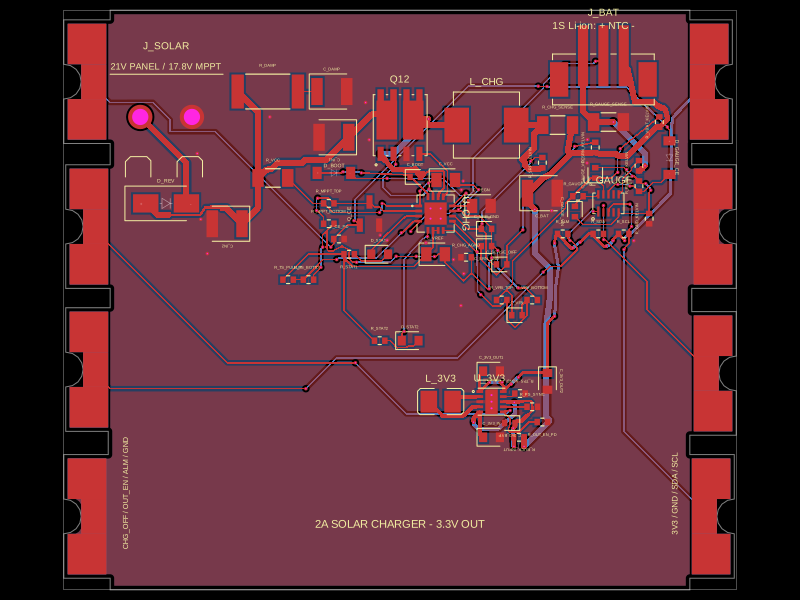 Similar packageShiboSoftwareDev/solar-battery-charger-moduleThis hardware setup integrates a solar panel, a lithium-ion battery, and a multi-rail buck converter with a battery charging IC, protection circuitry, and monitoring components, enabling solar power harvesting, battery charging, and power distribution in an embedded system.
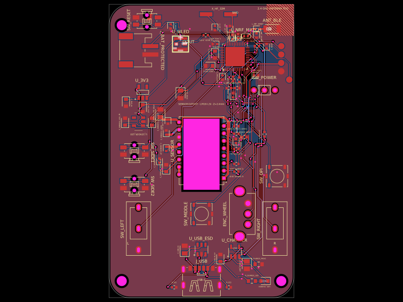 Discover something newMustafaMulla29/wireless-mouse-pcb