README.md
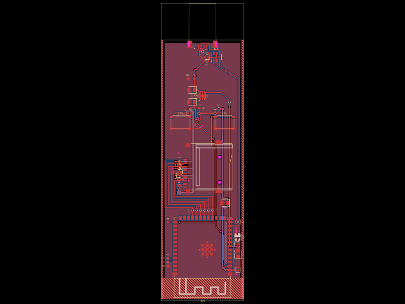
# nRF52810 + PMW3610 Bluetooth LE mouse

Two-layer wireless-mouse PCB, converted from PMW3360 to the lower-power
PMW3610DM-SUDU (JLCPCB `C42442560`). The board is
44 mm × 70 mm and all components are on the top side.

## Hardware

- bare `NRF52810-QFAA-R` Bluetooth LE SoC, 32 MHz crystal, SWD/reset pads,
  discrete RF matching network, and `2450AT18A100E` ceramic antenna
- PMW3610 optical sensor with LM18-LSI lens geometry and 1.9 V regulator
- left, right, middle, DPI, and optional side buttons
- EC10 mouse-wheel encoder
- protected one-cell LiPo input, power switch, AP2112K 3.3 V regulator, and
  switched battery-voltage divider
- USB-C charging-only input, 5.1 kOhm CC resistors, USB ESD protection, and
  MCP73831 charger configured for about 250 mA
- charge LED, addressable four-pin debug WLED, and SWD test points

USB-C does not carry mouse data. Mouse reports are sent over Bluetooth LE by
the firmware in [`firmware`](firmware/README.md).

## PMW3610 implementation

`imports/PMW3610DM_SUDU.tsx` is the exact imported `C42442560` part. Its lead
coordinates and 3D model are unchanged. Two local additions are intentional:

- pin 1 is expressed as an equivalent 0.7 mm circular drill inside the exact
  1.1 mm square copper pad, avoiding the invalid null drill generated by the
  imported overlapping primitives;
- the footprint owns the 16.96 mm × 8.60 mm through-board opening specified by
  PixArt Figure 5. This allows the LM18-LSI lens/baseplate assembly to sit
  through the PCB while keeping the component/cutout ownership explicit.

The sensor uses PixArt's Figure 6 supply, charge-pump, laser, reset, and
3-wire serial circuit. VDD is 1.9 V and VDDIO is 3.3 V. Its SPI-like signals
connect to the nRF52810 through 33 ohm series resistors.

Mechanical requirements from the PMW3610 datasheet:

- use the `LM18-LSI` lens/baseplate assembly;
- keep 7.40 mm from PCB top to the tracking surface;
- keep 2.40 mm from the lens reference plane to the tracking surface;
- the sensor package is qualified for no-wash wave soldering with a fixture
  that protects the sensor body. Confirm the assembler accepts that process;
  otherwise install the sensor separately according to PixArt's instructions.

## Validation

The final design was rebuilt and checked after the PMW3610 conversion:

- TypeScript: pass
- netlist: 0 errors, 0 warnings
- PCB placement: 0 errors, 0 warnings
- routing difficulty: completed
- full default autoroute: 157 traces, 0 empty routes
- post-build shorts/DRC: 0 errors
- Circuit JSON: one sensor-owned cutout, no null plated-hole IDs, four copper
  pours
- Gerber export: front/back copper, mask, paste, silkscreen, edge cuts, PTH and
  NPTH drills, BOM, and pick-and-place files are present
- BOM: `U_SENSOR` resolves to `C42442560`
- pick-and-place: `U_SENSOR` is top-side at 90 degrees
- Zephyr 4.4.2 firmware: clean nRF52810 build, 145,628 bytes flash and
  20,672 bytes RAM
- firmware pin map: checked against every named nRF52810 net in the PCB
- sensor orientation: the firmware applies the transform for the PCB's 90
  degree PMW3610 rotation; final cursor direction remains adjustable in
  firmware after the first physical tracking test

The current fabrication archive is:

`dist/wireless-mouse-pmw3610-gerbers.zip`

The compiled SWD image is:

`dist/firmware/pmw3610-ble-mouse.hex`

Schematic-placement still prints non-blocking readability suggestions for a
few grouped capacitors/crystal traces. Imported symbol/refdes and supplier
footprint-comparison warnings also remain. They are not DRC, connection, or
routing failures and no check is disabled.

## Before ordering

- Order from this project's fresh export, not the older published PMW3360 build.
- Confirm `C42442560` pre-order allocation and the assembler's through-hole,
  no-wash wave-solder process for the sensor.
- Confirm the real protected LiPo connector polarity: pin 1 is VBAT and pin 2
  is GND.
- Visually inspect every rotation in the assembly preview, especially USB-C,
  battery/power connectors, switches, encoder, charging LED, and WLED. Several
  imported parts do not expose supplier pin-1 metadata, so the exporter cannot
  automatically certify their rotations.
- Keep the antenna region free of copper, battery, enclosure metal, and other
  components.
- Charge with the mouse switched off; this first revision has no load-sharing
  power path.
- Program through SWD before functional testing. The PCB has no USB data path.
- After assembly, confirm cursor X/Y direction on a real surface. If an axis is
  reversed, change the documented PMW3610 transform flags and rebuild; no PCB
  change is required.

This is an electrically routed first prototype, not a guarantee of mechanical
enclosure fit, antenna match/range, optical tracking, or production yield.
Those require the assembled prototype, correct lens/baseplate, final enclosure,
and firmware testing.

## Commands

```sh
bun run typecheck
npx tsci check netlist
npx tsci check schematic-placement
npx tsci check placement
npx tsci check routing-difficulty
npx tsci build
```

Nothing from this migration has been published, ordered, committed, or pushed.