mohan-bee/compact-pir
Compact 3.3 V ESP8684 wireless motion/GPIO breakout board with LiPo regulation, 40 MHz crystal, U.FL antenna matching, digital PIR sensor, switched LED, decoupling, and dual 10-pin headers.
- Version
- 1.0.2
- License
- unset
- Stars
- 0
validation/geometry-check.json
{
  "input": "/Users/mohan/Documents/Codex/2026-10-24/use-esp8684h4x-and-the-pir-motion-2/work/registry-native/dist/index/circuit.json",
  "input_sha256": "67accdd9e31e17ec06e9e58eb5c6e34ad14065370df0b71a0fc4fe2f1332fa62",
  "reference": "/Users/mohan/Documents/Codex/2026-10-24/use-esp8684h4x-and-the-pir-motion-2/outputs/circuit.json",
  "scope": "Dimensions, allowed copper layers, source component/pin-net equivalence, full-width protected RF/crystal trace/via geometry, emitted build errors. Requires separate physical clearance/connectivity DRC.",
  "result": "FAIL",
  "board": {
    "width": 29,
    "height": 25,
    "num_layers": 2,
    "thickness": 1
  },
  "dimensions_29x25mm_two_layers": true,
  "counts": {
    "source_group": 1,
    "source_net": 29,
    "source_port": 118,
    "source_component": 34,
    "source_board": 1,
    "source_refdes_convention_warning": 2,
    "source_component_internal_connection": 1,
    "source_trace": 126,
    "source_no_power_pin_defined_warning": 2,
    "source_no_ground_pin_defined_warning": 1,
    "source_component_pins_underspecified_warning": 1,
    "schematic_component": 34,
    "schematic_text": 65,
    "schematic_group": 1,
    "schematic_port": 118,
    "schematic_line": 8,
    "schematic_symbol": 1,
    "schematic_path": 4,
    "schematic_trace": 91,
    "schematic_net_label": 30,
    "schematic_missing_sheet_warning": 1,
    "pcb_component": 34,
    "pcb_board": 1,
    "pcb_plated_hole": 20,
    "pcb_silkscreen_text": 55,
    "pcb_courtyard_rect": 28,
    "pcb_smtpad": 98,
    "pcb_solder_paste": 98,
    "pcb_silkscreen_path": 57,
    "pcb_courtyard_outline": 6,
    "pcb_silkscreen_circle": 2,
    "pcb_fabrication_note_path": 3,
    "pcb_port": 118,
    "pcb_fabrication_note_text": 1,
    "pcb_trace": 96,
    "cad_component": 34,
    "pcb_via": 95,
    "pcb_copper_pour": 14,
    "pcb_trace_error": 1,
    "source_project_metadata": 1
  },
  "component_references_equal": true,
  "normalized_pin_count": 118,
  "reference_pin_count": 118,
  "normalized_component_pin_net_differences": [],
  "invalid_copper_layers": [],
  "unresolved_trace_or_via_nets": [],
  "protected_rectangles_circuit_json_mm": {
    "rf_bottom_reference": [
      -13.7,
      -2.8,
      -6.1,
      3.1
    ],
    "crystal_bottom_reference": [
      -5.2,
      2.8,
      -0.65,
      7.9
    ]
  },
  "non_ground_bottom_trace_segments_checked": 375,
  "non_ground_via_records_checked": 73,
  "inline_route_via_points_checked": 107,
  "protected_region_violations": [],
  "invalid_route_geometry": [],
  "emitted_build_errors": [
    {
      "type": "pcb_trace_error",
      "pcb_trace_error_id": "pcb_trace_error_0",
      "error_type": "pcb_trace_error",
      "message": "PCB trace .J2 > .pin4 to net.GPIO1 is too close to .J2 > .pin3 to net.GPIO0 (gap: 0.072mm)",
      "pcb_trace_id": "source_net_3_0",
      "source_trace_id": "",
      "pcb_component_ids": [],
      "center": {
        "x": -7.324467335248016,
        "y": -0.4615347779127832
      },
      "pcb_port_ids": [
        "pcb_port_13",
        "pcb_port_33",
        "pcb_port_12",
        "pcb_port_32"
      ]
    }
  ]
}
Related Packages
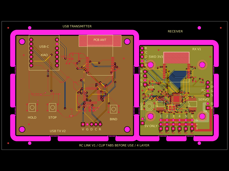 More from this authormohan-bee/rc-link-breakaway-panelA four-layer RC link panel combining an STM32/E28 2.4‑GHz transmitter with USB-RP2040 socket and an STM32/E28 receiver providing six buffered PWM servo outputs, regulated 3.3‑V power, headers, controls, and protection/decoupling.
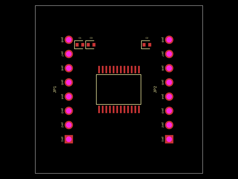 Similar packageimrishabh18/motor-driver-breakout"A 30x30mm TB6612FNG motor driver board with dual 8-pin headers and bypass capacitors for motor control and power regulation"
This summary captures the key physical characteristics:
- Uses TB6612FNG motor driver chip
- 30x30mm board size
- Dual 8-pin headers (JP1 and JP2)
- Includes decoupling capacitors (C1, C2, C3)
- Purpose is motor control and power management
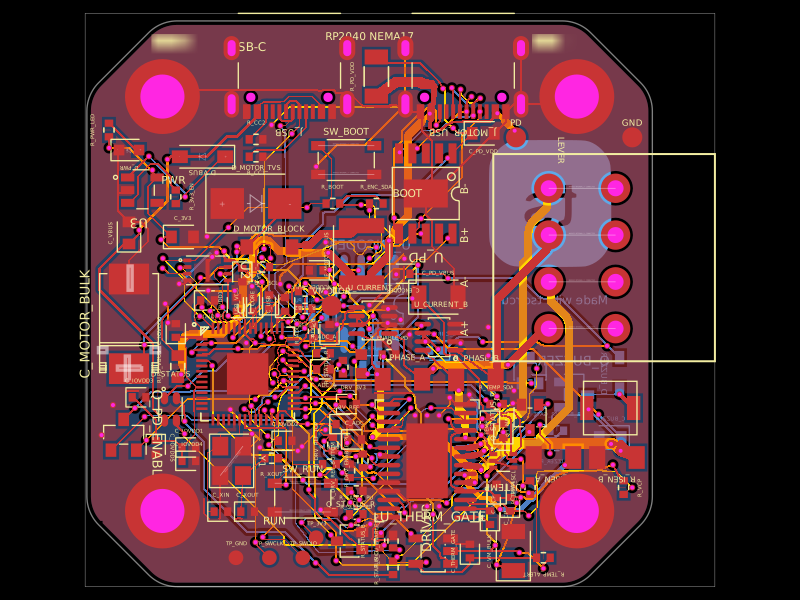 Discover something newastra/nema17-stepper-motor-controller-spring-clamp-rp2040A 4-layer RP2040 controller board that negotiates USB‑C PD motor power and drives a NEMA17 stepper via a DRV8825, with current sensing, thermal shutdown, RGB status LED, buzzer alarm, optional AS5600 encoder, protection/filtering, and test points.