mohan-bee/compact-pir
Compact 3.3 V ESP8684 wireless motion/GPIO breakout board with LiPo regulation, 40 MHz crystal, U.FL antenna matching, digital PIR sensor, switched LED, decoupling, and dual 10-pin headers.
- Version
- 1.0.2
- License
- unset
- Stars
- 0
firmware/README.md
# Compact motion firmware

ESP-IDF **v6.1**, target **esp32c2**, ESP8684H4X **revision 2.0**, **4 MB flash**, **40 MHz crystal**. The flash interface uses conservative 30 MHz DIO operation; this is separate from the crystal frequency. This firmware was compiled for the board; it has not been flashed or tested on physical hardware.

GPIO2 reads the S18-L262B-2 digital REL output with both internal pulls disabled. GPIO7 drives the active-HIGH LED transistor. The LED stays off for the first 60 seconds after boot, then turns on when the PIR output is HIGH. Each HIGH reading restarts a 10-second hold; the LED turns off 10 seconds after the last observed HIGH. The loop yields for 20 ms between samples. The 60-second startup allowance is an adjustable application choice, not a manufacturer-specified sensor warmup time.

UART0 logs startup, input changes, settle completion and LED state at 115200 baud. After startup settling, the CPU enters manual Light-sleep whenever the LED is off and PIR is LOW; GPIO2 HIGH wakes it. Logs are flushed before sleeping. The 64-bit ESP Timer advances across Light-sleep, preserving hold timing. UART input is not configured as a wake source; EN reset and manual BOOT programming remain available. Actual sleep current and wake behavior require board measurements. Wi-Fi and Bluetooth are not initialized in this bring-up application. The board's wireless hardware remains available for a later application. See the official [ESP32-C2 sleep APIs](https://docs.espressif.com/projects/esp-idf/en/v6.1/esp32c2/api-reference/system/sleep_modes.html) and [ESP Timer sleep behavior](https://docs.espressif.com/projects/esp-idf/en/v6.1/esp32c2/api-reference/system/esp_timer.html).

## Wire and flash

Use a **3.3 V logic** USB–UART adapter. Power the board from a protected single-cell LiPo connected to BAT/GND, or an appropriate current-limited bench supply at the battery input. The board has no charger. Do not apply 5 V to its GPIOs.

| USB–UART / jumper | Board header |
|---|---|
| Adapter TX | J1 pin 6, RX19 |
| Adapter RX | J1 pin 5, TX20 |
| Adapter GND | J1 pin 2, GND |
| Battery positive | J1 pin 1, BAT |
| Battery negative | J1 pin 2, GND |
| Boot jumper to GND | J1 pin 7, BOOT9 |
| Reset briefly to GND | J1 pin 4, EN |

1. Hold BOOT9 to GND. Leave IO8 (J1 pin 8) HIGH using its onboard pull-up.
2. Briefly connect EN to GND and release EN; keep BOOT9 LOW while entering download mode.
3. With Python 3.10 or newer, install the official flashing tool (`python -m pip install esptool==5.6.0`) and run the following from this firmware directory, replacing the port name:

   ```sh
   python -m esptool --chip esp32c2 --port /dev/cu.usbserial-XXXX --baud 115200 --before no-reset --after no-reset write-flash --flash-mode dio --flash-freq 30m --flash-size 4MB 0x0 bin/compact-motion-merged.bin
   ```

4. Disconnect BOOT9 from GND and reset EN again. The application now boots from flash. Use a serial terminal at 115200 baud for logs. There is no automatic DTR/RTS reset circuit on this PCB.

The merged image includes bootloader, partition table and application at their generated offsets. Flashing it replaces existing firmware. It does not change eFuses. To flash separate images instead, use the generated `bin/flash_args` from that directory; its paths refer to files in `bin/`.

Connect a small external LED anode to LED+ and cathode to LED−. The board already includes the 150 Ω series resistor. Fit the separate SB-F-11 Fresnel lens before checking PIR range. GPIO2 is connected to the sensor output and must remain an input; GPIO7 is shared with the LED driver.

## Build and configure

Install official [ESP-IDF v6.1](https://docs.espressif.com/projects/esp-idf/en/v6.1/esp32c2/get-started/index.html), activate its environment, and run:

```sh
idf.py set-target esp32c2
idf.py build
```

Use `idf.py menuconfig` → **Motion indicator** to change settle/hold seconds. `sdkconfig.defaults` selects the board's crystal, flash and chip revision. GPIO assignments are fixed in `main/main.c` to match the PCB.

Host timing checks do not require ESP-IDF:

```sh
mkdir -p build
cc -std=c11 -Wall -Wextra -Werror tests/motion_logic_test.c -o build/motion_logic_test
./build/motion_logic_test
```

These checks cover ignored startup pulses, exact timeout boundaries, retriggering, continuous motion, and millisecond counter rollover. They cannot verify physical power, radio performance, PIR operation or LED polarity.

## Included build

`bin/compact-motion-merged.bin` is the flashable merged image (192,128 bytes, offset `0x0`). Separate application, bootloader, partition table and generated flash arguments are also included. `bin/SHA256SUMS` records each binary's checksum. `validation/` contains the successful cross-build log, passing host test, inspected image headers and `build-info.json` with the exact ESP-IDF commit, compiler, settings and file hashes. Both application and bootloader report ESP32-C2, minimum revision 2.0, 4 MB, 30 MHz DIO, with valid image checksum and SHA hash. This verifies the build files; physical programming, PIR wake and current consumption remain untested.
Related Packages
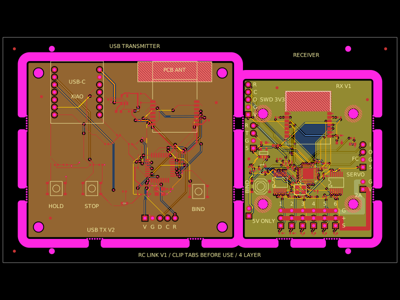 More from this authormohan-bee/rc-link-breakaway-panelA four-layer RC link panel combining an STM32/E28 2.4‑GHz transmitter with USB-RP2040 socket and an STM32/E28 receiver providing six buffered PWM servo outputs, regulated 3.3‑V power, headers, controls, and protection/decoupling.
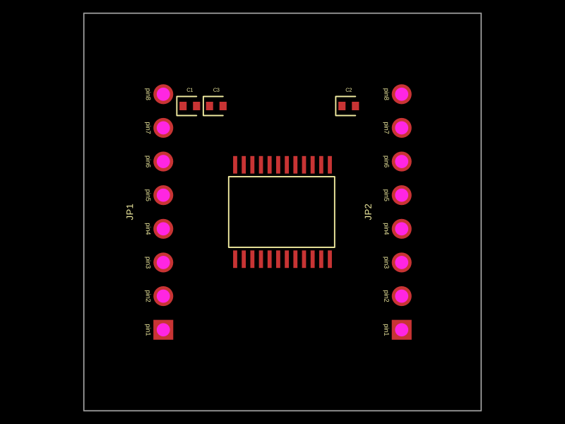 Similar packageimrishabh18/motor-driver-breakout"A 30x30mm TB6612FNG motor driver board with dual 8-pin headers and bypass capacitors for motor control and power regulation"
This summary captures the key physical characteristics:
- Uses TB6612FNG motor driver chip
- 30x30mm board size
- Dual 8-pin headers (JP1 and JP2)
- Includes decoupling capacitors (C1, C2, C3)
- Purpose is motor control and power management
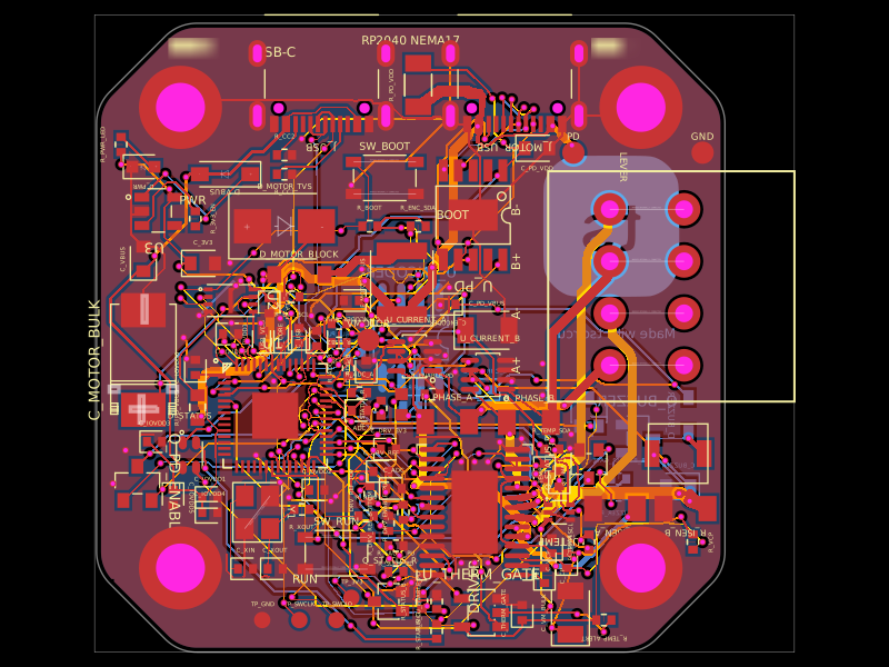 Discover something newastra/nema17-stepper-motor-controller-spring-clamp-rp2040A 4-layer RP2040 controller board that negotiates USB‑C PD motor power and drives a NEMA17 stepper via a DRV8825, with current sensing, thermal shutdown, RGB status LED, buzzer alarm, optional AS5600 encoder, protection/filtering, and test points.