imrishabh18/nema-23-stepper-controller
A 57 mm four-layer RP2040 NEMA23 stepper-controller PCB with USB‑C/USB‑PD power input, protected motor rail, DRV8452 dual-winding driver, bidirectional current sensing, temperature/enable interlock, optional magnetic encoder, RGB LED and buzzer status indicators, and motor/test connectors.
- Version
- 1.2.3
- License
- unset
- Stars
- 0
verification.md
# Revision E validation

Validated design revision E (1.2.3-local). Full release checks passed at 2026-10-02T20:16:50.377Z.

| Check | Result |
|---|---|
| Latest installed tscircuit / CLI / EasyEDA-converter | 0.0.2729 / 0.1.2228 / 0.0.364 |
| TypeScript and source audits | Pass; 10 reproducible non-IC imported symbols; standard native USB-C connectors; native yellow IC boxes; no fixed component schX/schY |
| Electrical calculations and netlist | Pass; 0 netlist errors and warnings |
| Standard page format | All sheets A4 (297 × 210 mm), with no content outside the drawing area |
| Schematic placement | Zero issues; no waived findings |
| PCB placement and independent DRC | Pass; 0 errors |
| Power routing | All 144 supply, charge-pump and load traces on top/bottom; GND may use inner layers |
| Gerber-derived shorts | None on top, inner1, inner2 or bottom |
| Physical ground connectivity | One connected network, including plated barrels and with drills subtracted |
| Kelvin branches | All four sense paths separate from load copper outside their shunt pads |
| Local preview | Canvas renders the complete board with zero circuit errors; Canvas remains the default after refresh |

The build contains 124 source components, 168 PCB components, 361 PCB traces, 321 vias and 17 schematic sheets. The optional bottom encoder and its two bypass capacitors remain DNP.

Circuit JSON SHA-256: `3c739af8ea21ea91aa7479eced5bc19aacb29d98d36729119ea68bf8d02cb01a`.

`checks/release/inputs.json` identifies the exact design and validation-script inputs. Detailed logs and the independent DRC, power-layer, ground-copper, Kelvin and schematic-analysis reports are included in `checks/`. `delivery-manifest.json` covers every delivered file other than itself, including documentation and the separately verified preview launcher.

## Routing and symbols

All 456 source traces retain their physical pin connectivity. The schematic-only 1.2.3 update changed no PCB port locations or copper paths. In the earlier DRV8452 migration, its new EasyEDA lead lands moved the 44 lead centres by approximately 0.077 mm; saved route endpoints were updated against the same physical pins. Two signal vias were moved outward to clear the new exposed pad. The exposed pad uses the new 7.6 × 3.4 mm geometry. The saved router still checks its complete input fingerprint, and the complete new board passed DRC and copper checks. Ground may use inner copper; all supply and motor-output routes remain on the outer layers. The BOOT ground bridge and dedicated Kelvin branches remain.

The board now uses DRV8452DDWR / C5624514, 2.61 kΩ / 10 kΩ VREF divider, WSLP1206R0100FEA / C844910 phase shunts and SMBJ33A / C224019 TVS. Nominal full scale is 3.965 A peak / 2.804 A RMS; the two ADC channels have 0.2 V/A sensitivity. Calibration, temperature-dependent derating and motor-body mounting requirements are in README.md. The profile is design data; firmware has not been implemented.

Both USB-C ports use the native standard connector symbol and retain every physical contact. The power receptacle exposes all 20 contacts, including four VBUS and four GND pins, through `usb-c-compat.ts`; only the native arrangement is extended, with no custom drawing or fixed pin coordinates.

EasyEDA source records, converter versions and generated-symbol hashes are included. Native tscircuit autolayout places components within functional sections and seventeen standard A4 sheets with explanatory section text. Local artwork coordinates, diode orientations and reference labels are part of the imported symbol definitions. `symbol-text-compat.ts` fixes current-core text ownership and redundant custom-resistor pin labels without placing components. `schematic-section-notes.ts` keeps explanatory notes above rendered rail labels and wraps them to section width after native placement.

Compact native grids keep decoupling banks together, and native match-pack places the two current-sense channel groups independently. Every schematic-analysis finding fails validation; no waivers remain. The section compatibility helper preserves the native grid mode for grouped section members.

## Preview and limitations

Run `bun install --frozen-lockfile`, then `node start-preview.mjs` in the delivered folder. This uses the CLI's supported standalone override to select Canvas by default; experimental WebGPU currently rejects through-pad trace geometry. Installed dependencies and circuit data are untouched. Direct `bun run dev` users can right-click the PCB and select Rendering Engine → Canvas.

Rear silkscreen retains DATA/PWR, the tscircuit logo, attribution, board name and revision markings. The bottom PNG is flipped to show the physical underside. Source/render checks are complete; no firmware, physical prototype, manufacturer DFM approval or bench validation is supplied. Current calibration, power sequencing, thermal behavior, motor/encoder fit and EPR interoperability still require hardware validation. The README records the GPIO and operating requirements.

The compiler's React key diagnostic and saved-router export notice are informational. No circuit errors or shorts remain. This validation applies to the delivered revision E files. Publication, when performed, is recorded separately in outputs/published-release.json.
Related Packages
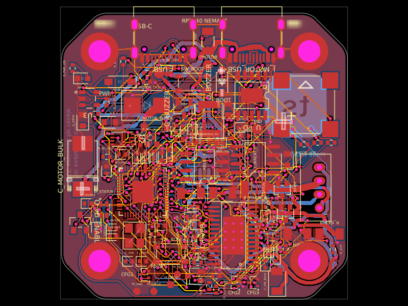 More from this authorimrishabh18/rp2040-motor-controllerA 4-layer RP2040-based USB-C/USB-PD controller board that powers and drives a NEMA17 stepper via a DRV8825, with current/temperature telemetry, RGB and buzzer status indicators, QSPI flash, protection/filtering, test points, and optional AS5600 encoder support.
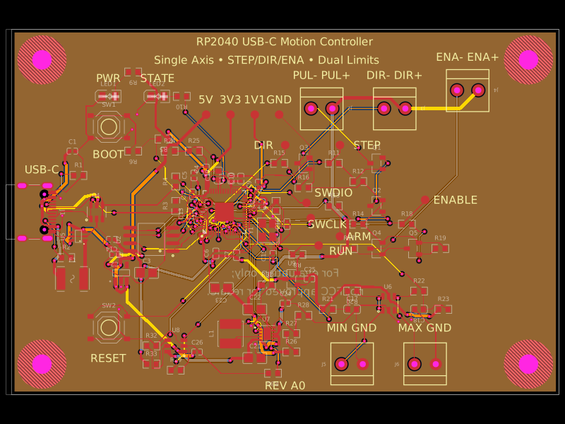 Similar packageAnasSarkiz/rp2040-usb-c-single-axis-dm542t-motion-controller--01a0e89cA USB‑C RP2040 controller board with external QSPI flash, crystal clock, regulated 3.3/1.1/5 V power, boost-converted motor-driver supply, protected USB and limit inputs, status LEDs, reset/boot switches, and AO3400A MOSFET outputs for stepper-control signals.
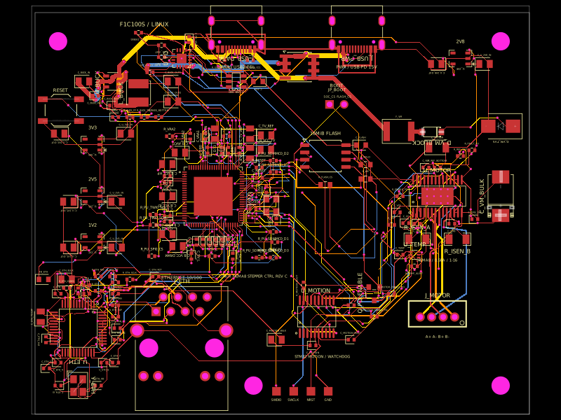 Discover something newshibosoftwaredev/f1c100s-linux-nema8-stepper-controllerA four-layer Linux motion-control carrier board combining an Allwinner F1C100S SoC, USB-C PD power, 10/100 Ethernet, STM32 watchdog-controlled DRV8825 NEMA-8 stepper drive, SPI flash, regulated power rails, USB protection, and supporting connectors/passives.