hrithik18k/smart-switch-pcb
The AO3400A component models a SOT-23 N-channel MOSFET with labeled pins for Gate, Source, and Drain, including 3D CAD models and schematic symbols for electronic circuit design.
- Version
- 1.0.1
- License
- unset
- Stars
- 0
imports/G5RL_1A_E_HR_DC5.tsx
import type { ChipProps } from "@tscircuit/props";

const pinLabels = {
  pin1: ["pin1", "COIL_A"],
  pin3: ["pin3", "COM_A"],
  pin4: ["pin4", "COM_B"],
  pin5: ["pin5", "NO_A"],
  pin6: ["pin6", "NO_B"],
  pin8: ["pin8", "COIL_B"],
} as const;

export const G5RL_1A_E_HR_DC5 = (props: ChipProps<typeof pinLabels>) => {
  return (
    <chip
      pinLabels={pinLabels}
      symbol={
        <symbol>
          <schematicrect
            schX={0.02}
            schY={0}
            width={1.36}
            height={1.4}
            color="#880000"
          />
          <schematicpath
            points={[
              { x: 0.3, y: 0.26 },
              { x: 0.36, y: 0.24 },
            ]}
            strokeColor="#880000"
          />
          <schematicpath
            points={[
              { x: 0.6, y: 0 },
              { x: 0.6, y: 0.26 },
              { x: 0.3, y: 0.26 },
              { x: 0.36, y: 0.28 },
            ]}
            strokeColor="#880000"
          />
          <schematicpath
            points={[
              { x: 0.3, y: 0 },
              { x: 0.3, y: 0.1 },
              { x: 0.2, y: 0.3 },
            ]}
            strokeColor="#880000"
          />
          <port
            name="pin8"
            pinNumber={8}
            aliases={["8"]}
            direction="down"
            schX={-0.5}
            schY={-1.1}
            schStemLength={0.4}
          />
          <port
            name="pin6"
            pinNumber={6}
            aliases={["6"]}
            direction="down"
            schX={0.3}
            schY={-1.1}
            schStemLength={0.4}
          />
          <port
            name="pin5"
            pinNumber={5}
            aliases={["5"]}
            direction="down"
            schX={0.6}
            schY={-1.1}
            schStemLength={0.4}
          />
          <port
            name="pin4"
            pinNumber={4}
            aliases={["4"]}
            direction="up"
            schX={0.6}
            schY={1.1}
            schStemLength={0.4}
          />
          <port
            name="pin3"
            pinNumber={3}
            aliases={["3"]}
            direction="up"
            schX={0.3}
            schY={1.1}
            schStemLength={0.4}
          />
          <port
            name="pin1"
            pinNumber={1}
            aliases={["1"]}
            direction="up"
            schX={-0.5}
            schY={1.1}
            schStemLength={0.4}
          />
          <schematicpath
            points={[
              { x: 0.6, y: 0 },
              { x: 0.6, y: -0.3 },
            ]}
            strokeColor="#880000"
          />
          <schematicpath
            points={[
              { x: 0.3, y: 0 },
              { x: 0.3, y: -0.3 },
            ]}
            strokeColor="#880000"
          />
          <schematicpath
            points={[
              { x: -0.5, y: -0.3 },
              { x: -0.5, y: -0.1 },
            ]}
            strokeColor="#880000"
          />
          <schematicpath
            points={[
              { x: -0.5, y: 0.1 },
              { x: -0.5, y: 0.3 },
            ]}
            strokeColor="#880000"
          />
          <schematicrect
            schX={-0.51}
            schY={0}
            width={0.18}
            height={0.2}
            color="#880000"
          />
        </symbol>
      }
      supplierPartNumbers={{
        jlcpcb: ["C113250"],
      }}
      manufacturerPartNumber="G5RL-1A-E-HR-DC5"
      footprint={
        <footprint>
          <platedhole
            shape="circle"
            portHints={["pin8"]}
            pcbX={-12.5}
            pcbY={3.75}
            outerDiameter="2.5mm"
            holeDiameter="1.5mm"
          />
          <platedhole
            shape="circle"
            portHints={["pin6"]}
            pcbX={7.5}
            pcbY={3.75}
            outerDiameter="2.5mm"
            holeDiameter="1.5mm"
          />
          <platedhole
            shape="circle"
            portHints={["pin5"]}
            pcbX={12.5}
            pcbY={3.75}
            outerDiameter="2.5mm"
            holeDiameter="1.5mm"
          />
          <platedhole
            shape="circle"
            portHints={["pin1"]}
            pcbX={-12.5}
            pcbY={-3.75}
            outerDiameter="2.5mm"
            holeDiameter="1.5mm"
          />
          <platedhole
            shape="circle"
            portHints={["pin3"]}
            pcbX={7.5}
            pcbY={-3.75}
            outerDiameter="2.5mm"
            holeDiameter="1.5mm"
          />
          <platedhole
            shape="circle"
            portHints={["pin4"]}
            pcbX={12.5}
            pcbY={-3.75}
            outerDiameter="2.5mm"
            holeDiameter="1.5mm"
          />
          <silkscreenrect width="29mm" height="12.7mm" strokeWidth="0.2mm" />
          <courtyardrect width="30mm" height="13.7mm" />
        </footprint>
      }
      cadModel={{
        objUrl:
          "https://modelcdn.tscircuit.com/easyeda_models/assets/C113250.obj?uuid=1abe27a32bae46d08f6f49a81d4e826b",
        stepUrl:
          "https://modelcdn.tscircuit.com/easyeda_models/assets/C113250.step?uuid=1abe27a32bae46d08f6f49a81d4e826b",
        pcbRotationOffset: 0,
        modelOriginPosition: {
          x: 0.3230117999999891,
          y: -0.012001500000010878,
          z: -0.500006,
        },
      }}
      {...props}
    />
  );
};
Related Packages
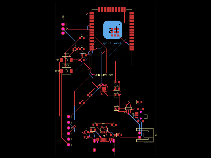 More from this authorhrithik18k/air-mouseThis code defines various surface-mount and through-hole electronic components, specifying their physical footprints, pin configurations, and 3D CAD models for hardware visualization.
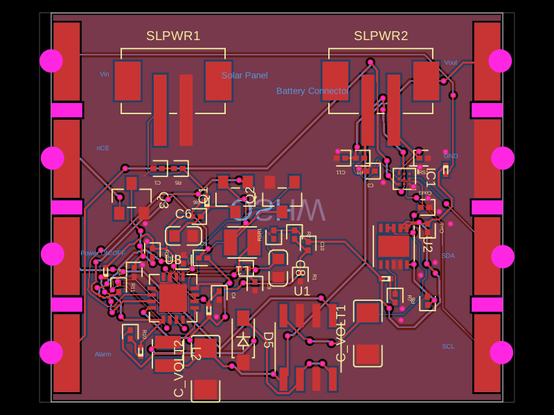 Similar packageShiboSoftwareDev/solar-battery-chargerThis code defines various surface-mount and through-hole electronic components (like diodes, voltage regulators, and ICs) with detailed footprints, 3D models, and pin configurations for PCB design.
 Discover something newShiboSoftwareDev/mspm0g3507-usb-c-dev-boardThe circuit assembles a USB-C port with integrated ESD protection, power regulation, UART interface, and microcontroller (MSPM0G3507) with supporting components for USB data lines, CC termination, I2C, SPI, reset circuitry, and indicator LEDs.