astra/nema17-stepper-motor-controller-spring-clamp-rp2040
A 4-layer RP2040 controller board that negotiates USB‑C PD motor power and drives a NEMA17 stepper via a DRV8825, with current sensing, thermal shutdown, RGB status LED, buzzer alarm, optional AS5600 encoder, protection/filtering, and test points.
- Version
- 1.4.0
- License
- unset
- Stars
- 0
schematic/MotorOutputsSection.tsx
import { motorTrace, schematicSections, schematicSheets } from "./config";

// WAGO 2601-1104, manufacturer drawing dated 2023-07-02.
// Four independent potentials; two solder tails per potential, 5 mm apart.
// 3.5 mm pole pitch, 1.2 mm finished drills, 15.5 x 16.58 mm envelope; 12.75 mm installed height.
export const MotorOutputConnectors = () => (
  <connector name="J1" allowOffBoard
    manufacturerPartNumber="2601-1104"
    supplierPartNumbers={{jlcpcb:["C7472748"]}}
    cadModel={{
      objUrl: "https://modelcdn.tscircuit.com/easyeda_models/assets/C7472748.obj?uuid=22ce918216fc4a618b4f2399cefec1f6",
      stepUrl: "https://modelcdn.tscircuit.com/easyeda_models/assets/C7472748.step?uuid=22ce918216fc4a618b4f2399cefec1f6",
      pcbRotationOffset: 0,
      // Supplier model origin, relative to the existing eight-tail footprint.
      modelOriginPosition: { x: -0.8514994, y: 6.202823, z: 1.573692 },
    }}
    pinLabels={{pin1:["A_PLUS"],pin2:["A_MINUS"],pin3:["B_PLUS"],pin4:["B_MINUS"],pin5:["A_PLUS_TAIL"],pin6:["A_MINUS_TAIL"],pin7:["B_PLUS_TAIL"],pin8:["B_MINUS_TAIL"]}}
    internallyConnectedPins={[[1,5],[2,6],[3,7],[4,8]]}
    pcbPinLabels={{pin1:"A+",pin2:"A-",pin3:"B+",pin4:"B-"}}
    pcbX={21.525} pcbY={11.64} pcbRotation={90}
    schX={9} schY={-1.5}
    schPinArrangement={{leftSide:{pins:[1,2,3,4,5,6,7,8],direction:"top-to-bottom"}}}
    schSheetName={schematicSheets.motorDriver}
    schSectionName={schematicSections.motorOutputs}
    footprint={
      <footprint insertionDirection="from_y_neg">
        {[-5.25,-1.75,1.75,5.25].flatMap((x,i) => [-2.5,2.5].map(y => (
          <platedhole pcbX={x} pcbY={y} portHints={[String(i+1+(y<0?4:0))]}
            shape="circle" holeDiameter={1.2} outerDiameter={2.2} />
        )))}
        <silkscreenrect pcbX={0.06} pcbY={-1.64} width={15.5} height={16.58} strokeWidth={0.15}/>
        <courtyardrect pcbX={0.06} pcbY={-1.64} width={16} height={17.08}/>
        {[-5.25,-1.75,1.75,5.25].map((x,i) => (
          <silkscreentext pcbX={x} pcbY={8.8} text={["A+","A-","B+","B-"][i]} fontSize={0.8}/>
        ))}
        <silkscreentext pcbX={8.1} pcbY={1.575} pcbRotation={-90} text="LEVER" fontSize={0.65}/>
      </footprint>
    }
  />
);

export const MotorOutputTraces = () => (
	<>
		{/* Reserve room for the wider motor routes before the remaining signals. */}
		<trace
			name="MOTOR_A_PLUS"
			from=".DRIVER > .AOUT1"
			to=".R_PHASE_A > .pin1"
			schDisplayLabel="A_DRIVE"
			{...motorTrace}
		/>
		<trace
			name="MOTOR_A_MINUS"
			from=".DRIVER > .AOUT2"
			to=".J1 > .pin2"
			schDisplayLabel="A-"
			{...motorTrace}

		/>
		<trace
			name="MOTOR_B_PLUS"
			from=".DRIVER > .BOUT1"
			to=".R_PHASE_B > .pin1"
			schDisplayLabel="B_DRIVE"
			{...motorTrace}
		/>
		<trace
			name="MOTOR_B_MINUS"
			from=".DRIVER > .BOUT2"
			to=".J1 > .pin4"
			schDisplayLabel="B-"
			{...motorTrace}
		/>
	</>
);
Related Packages
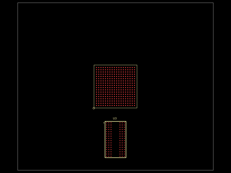 More from this authorastra/am3352-ram-test-blankA 324-ball TI AM3352 ARM processor/SoC footprint with DDR, LCD, USB, Ethernet, MMC, GPMC, serial, SPI/I²C, audio, ADC, clock, power, and JTAG interfaces, plus DDR routing constraints.
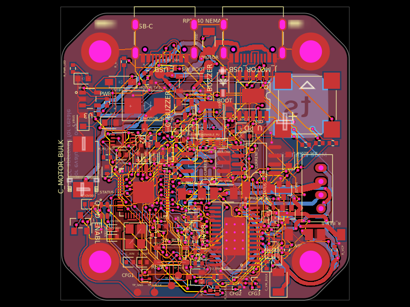 Similar packageimrishabh18/rp2040-motor-controllerA four-layer RP2040-based NEMA17 stepper controller with USB-C power/data, CH224K USB-PD negotiation, DRV8825 dual H-bridge drive, current/temperature telemetry, RGB status LED, buzzer alarm, QSPI flash, and optional AS5600 encoder.
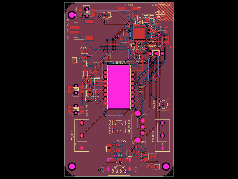 Discover something newMustafaMulla29/wireless-mouse-pcbA hardware component library defining footprints and 3D models for a 3.3 V regulator, RF antenna, switches, connectors, battery charger, and nRF52810 Bluetooth microcontroller.