astra/nema17-stepper-motor-controller-spring-clamp-rp2040
A 4-layer RP2040 controller board that negotiates USB‑C PD motor power and drives a NEMA17 stepper via a DRV8825, with current sensing, thermal shutdown, RGB status LED, buzzer alarm, optional AS5600 encoder, protection/filtering, and test points.
- Version
- 1.4.0
- License
- unset
- Stars
- 0
mechanical/README.md
# NEMA 17 rear-mounted controller

The outline follows the PD-Stepper V1.1 Gerber perimeter from joshr120/PD-Stepper, commit `3c40073a0ec51653f6ea48c70f365bd7f9f3bdcc`:
https://github.com/joshr120/PD-Stepper/tree/3c40073a0ec51653f6ea48c70f365bd7f9f3bdcc/PCB

- Overall outline: approximately 42.30 × 42.32 mm.
- Four mounting centers: (±15.5, ±15.5) mm, giving a 31 × 31 mm square.
- Mounting drill: 3.3 mm. Grounded 5.6 mm copper rings; placement reserves a 6.5 mm screw-head clearance circle.
- The perimeter's 3 mm corner transitions are approximated with 12 straight segments per 45-degree arc (maximum deviation approximately 0.002 mm).
- The optional AS5600 remains DNP at (0, 0) on the underside. Nine populated support parts are also on the underside; see the main README and assembly CPL. Use insulated spacers. The smaller buzzer is at (18, −7.8) mm on top.
- PD-Stepper includes a 2.5 mm heat-spreader model and only the central encoder on its underside. Our spacer must clear the particular motor’s rear shaft/bearing boss, the encoder (approximately 1.75 mm high), the magnet and protruding connector leads. Choose its thickness from that mechanical stack and the required magnetic sensing gap; the reference thickness is not a verified fit for this board. Screw length depends on motor length and the spacer/cover stack.
- The reference cover/heatspreader is not interchangeable: this design has different components, connector openings and thermal-contact positions.
- Motor connector: WAGO 2601-1104 (JLCPCB C7472748), four hinged levers, 3.5 mm pitch, eight solder tails. Side entry, parallel to the PCB and outward from the right edge. Envelope 15.5 × 16.58 mm, approximately 12.75 mm above the PCB. The approved envelope extends approximately 4.7 mm beyond the right board edge. Allow lever access above and wire access beyond the edge.

NEMA 17 describes the motor frame; check the actual motor's rear fasteners before ordering boards. The reference uses replacement motor tie screws. The PCB measures nearby driver-board temperature, not winding temperature.

The sampled perimeter is adapted from the PD-Stepper V1.1 Gerbers. The upstream GPL-3.0 license is included as `PD-Stepper-LICENSE`. This repository contains the modified outline source.

## Encoder magnet

The board origin must align with the motor shaft. Fit a diametrically magnetized on-axis magnet to an accessible rear shaft, facing the AS5600. The exact magnet, holder and axial gap depend on the motor, which has not been specified. Start from the sensor manufacturer’s magnet guidance and adjust until the firmware reports a valid field through a full revolution. Ensure the magnet cannot strike the chip and keep the buzzer opening clear. This is single-turn position sensing; there is no shaft pass-through hole at the board centre.
Related Packages
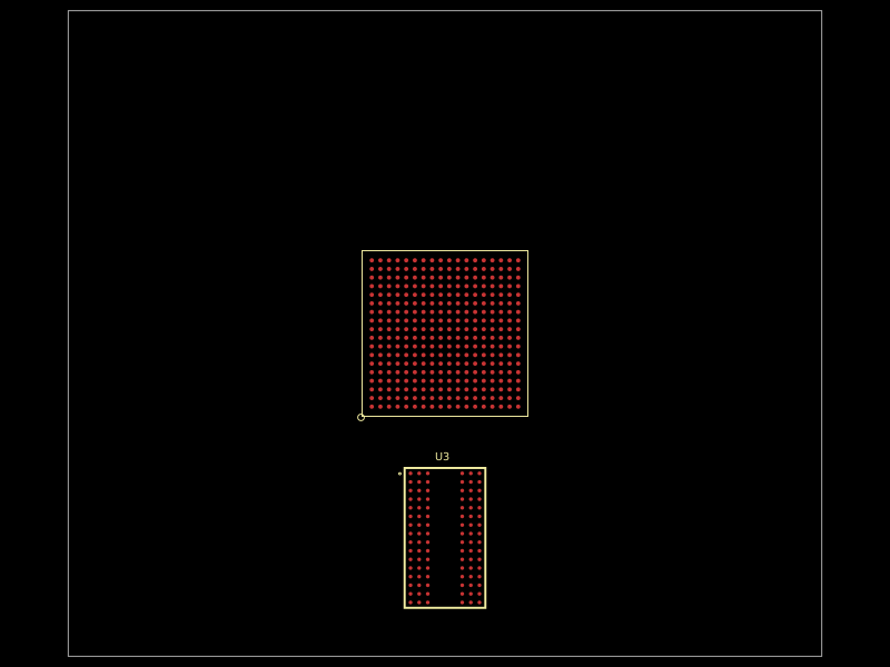 More from this authorastra/am3352-ram-test-blankA 324-ball TI AM3352 ARM processor/SoC footprint with DDR, LCD, USB, Ethernet, MMC, GPMC, serial, SPI/I²C, audio, ADC, clock, power, and JTAG interfaces, plus DDR routing constraints.
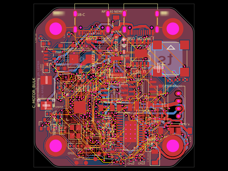 Similar packageimrishabh18/rp2040-motor-controllerA four-layer RP2040-based NEMA17 stepper controller with USB-C power/data, CH224K USB-PD negotiation, DRV8825 dual H-bridge drive, current/temperature telemetry, RGB status LED, buzzer alarm, QSPI flash, and optional AS5600 encoder.
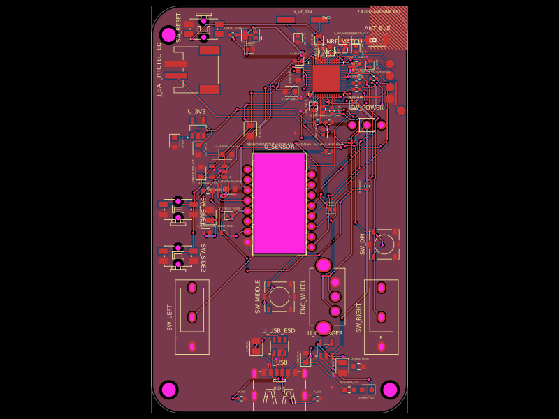 Discover something newMustafaMulla29/wireless-mouse-pcbA hardware component library defining footprints and 3D models for a 3.3 V regulator, RF antenna, switches, connectors, battery charger, and nRF52810 Bluetooth microcontroller.