astra/nema17-stepper-motor-controller-spring-clamp-rp2040
A 4-layer RP2040 controller board that negotiates USB‑C PD motor power and drives a NEMA17 stepper via a DRV8825, with current sensing, thermal shutdown, RGB status LED, buzzer alarm, optional AS5600 encoder, protection/filtering, and test points.
- Version
- 1.4.0
- License
- unset
- Stars
- 0
VALIDATION.md
# Lever connector revision 1.4.0 validation — 2026-09-28

Circuit JSON SHA-256: `6168bd8088646af2ad3acc1a8d587e1e299f41d2b06c0f2df26a75ad552110e1`

- Exact C7472748 supplier OBJ/STEP model assigned to J1; generated 3D board preview visually reviewed.
- Copper traces, vias, pads, drill geometry, outline and ground pours match 1.3.1 exactly. The connector body, CAD model, BOM and schematic part identity change to the side-entry part.
- Pinned tscircuit build and TypeScript typecheck: passed.
- Circuit regression tests: 21 passed, 0 failed, 2581 assertions.
- Firmware host tests: 23 passed, including the 4 kHz alarm setting.
- Exact original outline equality verified: 42.30 × 42.32 mm; original mounting holes retained.
- Embedded DRC and independent routing errors: 0.
- CLI check: 0 errors, 135 nonblocking warnings. These include supplier footprint comparisons, catalog/metadata, trace-length and schematic guidance; see reports/tsci-check.log.
- Gerber-derived shorts check: no shorts on all four copper layers.
- Physical ground audit: one connected network with six retained pour regions. Geometry-guarded selection removes 91 independently identified floating pour fragments before final DRC.
- All six motor paths retain the regression limits: at least 0.35 mm width, continuous sub-0.5 mm necks shorter than 1.5 mm, estimated individual trace resistance below 0.05 ohm at 20°C assuming 18 µm copper, no more than three vias per path. This is not thermal qualification.
- Connector regression verifies eight 1.2 mm holes, 3.5 mm pole pitch, 5 mm row spacing, paired tails and four isolated motor potentials.
- Placement was checked with routing disabled. Final routing and stale-route/pour guards are enabled.
- PCB top and bottom views, motor-driver and alarm schematics visually reviewed. Schematic snapshot updated.
- Validation, physical ground and fabrication audit hashes match the delivered circuit JSON.

J1 is WAGO 2601-1104, JLCPCB C7472748, with four horizontal hinged levers and side wire entry. BZ1 is the smaller KLJ-4020, C556936; D_BUZZER is B5819WS, C64886. The outline and all test points are retained. Nine populated support components are on the underside: the SMT BOM/CPL contains 91 top and nine bottom placements. Review bottom-side placement rotations with the assembler. The optional encoder remains DNP. J1 is excluded from SMT files and included in manual-assembly-bom.csv for wave or hand soldering of all eight tails.

The connector is approximately 12.75 mm high and extends approximately 4.7 mm past the right PCB edge, as approved. Wire entry faces outward parallel to the PCB; allow additional lever/wire access. This revision has not been fabricated or tested on physical hardware. Verify connector fit, underside and motor/enclosure clearance, alarm loudness and operation on a prototype. Retain baseline current, thermal and power-transient acceptance checks.
Related Packages
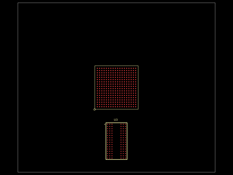 More from this authorastra/am3352-ram-test-blankA 324-ball TI AM3352 ARM processor/SoC footprint with DDR, LCD, USB, Ethernet, MMC, GPMC, serial, SPI/I²C, audio, ADC, clock, power, and JTAG interfaces, plus DDR routing constraints.
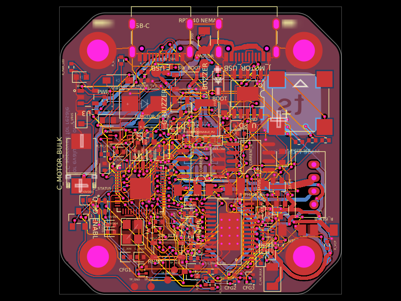 Similar packageimrishabh18/rp2040-motor-controllerA four-layer RP2040-based NEMA17 stepper controller with USB-C power/data, CH224K USB-PD negotiation, DRV8825 dual H-bridge drive, current/temperature telemetry, RGB status LED, buzzer alarm, QSPI flash, and optional AS5600 encoder.
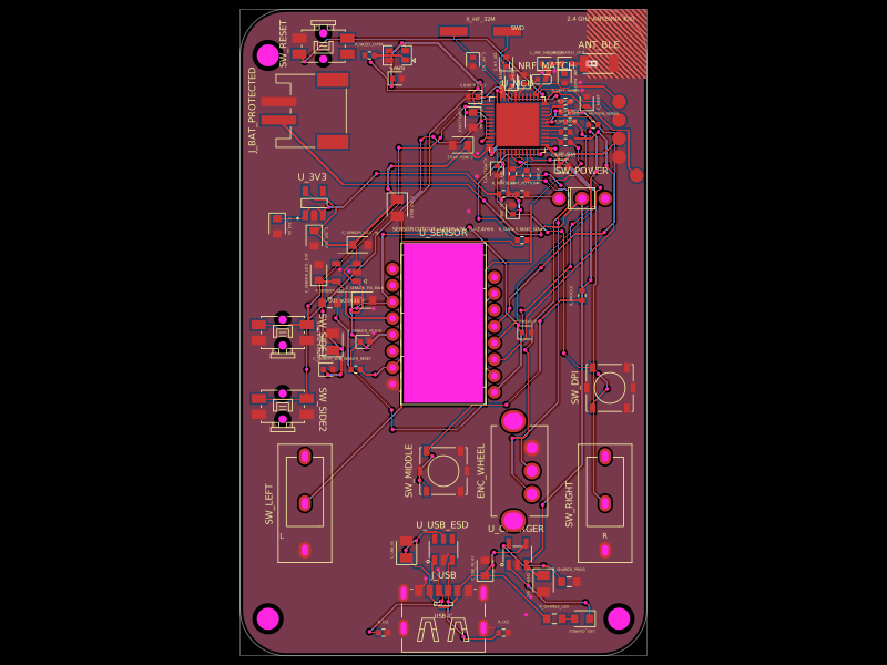 Discover something newMustafaMulla29/wireless-mouse-pcbA hardware component library defining footprints and 3D models for a 3.3 V regulator, RF antenna, switches, connectors, battery charger, and nRF52810 Bluetooth microcontroller.