astra/nema17-stepper-motor-controller-spring-clamp-rp2040
A 4-layer RP2040 controller board that negotiates USB‑C PD motor power and drives a NEMA17 stepper via a DRV8825, with current sensing, thermal shutdown, RGB status LED, buzzer alarm, optional AS5600 encoder, protection/filtering, and test points.
- Version
- 1.4.0
- License
- unset
- Stars
- 0
README.md
# RP2040 NEMA17 controller — side-entry lever revision

Revision 1.4.0 replaces the vertical-entry connector with WAGO 2601-1104. The wires enter horizontally, parallel to the PCB, from the right edge. The approved connector envelope overhangs that edge by approximately 4.7 mm; the PCB outline and mounting holes are unchanged.

## Motor connection

J1 is **WAGO 2601-1104**, **JLCPCB C7472748**. Each of the four isolated motor terminals has a hinged lever that holds the clamp open for wire insertion and closes to secure it. Wire entry faces outward from the right edge, parallel to the PCB. Open a lever, insert a stripped conductor, and close the lever. Disconnect power before changing motor wiring.

From bottom to top in the PCB top view (USB ports at the top), the terminals are **A+, A−, B+, B−**. Connect one winding across each pair. All eight solder tails must be soldered; pairs 1+5, 2+6, 3+7 and 4+8 represent the four terminals.

The manufacturer specifies 8–9 mm strip length and 0.2–1.5 mm² fine-stranded conductors for this version. Confirm the current datasheet for the particular conductor and ferrule. The controller remains limited to approximately 1 A peak winding current.

## Mechanical and electrical changes

- Exact original **42.30 × 42.32 mm** outline, four layers, 1.6 mm board thickness.
- Four 3.3 mm mounting holes remain on the original 31 × 31 mm square.
- The connector envelope is 15.5 × 16.58 mm and extends approximately 4.7 mm beyond the right PCB edge. Installed height is 12.75 mm; allow additional clearance above the levers and outside the board for wire insertion.
- BZ1 is now a **KELIKING KLJ-4020**, **C556936**, 4 × 4 × 2 mm passive magnetic buzzer. Firmware drives it at 4 kHz.
- D_BUZZER uses a smaller B5819WS, **C64886**, retaining the flyback diode function.
- Nine support components move to the underside: Q_BUZZER, D_BUZZER, R_BUZZER_GATE, R_BUZZER_PD, C_BUZZER, Q_STATUS_G, R_PD_ENABLE_PU, C_CURRENT_A and C_CURRENT_B. This requires **two-sided SMT assembly**.
- All test points remain. PD, driver, processor and current-sense support placement and affected routes have been revised. The optional underside AS5600 remains DNP.

Use insulated spacers that clear underside components, protruding connector pins, solder joints and the motor's rear shaft/bearing boss. The original reference heat-spreader/cover is not interchangeable. Preserving the PCB outline does not preserve the previous component-height envelope.

## Files and assembly

`dist/index/gerbers.zip` contains fabrication outputs. The assembly BOM and CPL include the SMT components on both sides and exclude the DNP encoder and bare PCB features. J1 is listed separately in `manual-assembly-bom.csv` with its JLCPCB number because it requires a through-hole assembly operation. Arrange through-hole assembly with the assembler or hand solder it after SMT assembly. Review bottom-side rotations and the connector assembly process with the assembler before production.

See `VALIDATION.md` and `reports/` for the current checks. This design has not been fabricated or physically tested. Connector fit, access, underside clearance, alarm loudness, current sensing, temperature and power transients require prototype checks.

```sh
bun install --frozen-lockfile
bun run typecheck
bun run build
bun run validate:build
bun run test:built
bun run check:built
bun run test:firmware
bun run dev --port 3020
```

`bun scripts/render-placement.tsx` checks placement with routing disabled. Final routing and geometry guards are enabled in the normal entry point. The physical ground audit uses Python with shapely: `python3 scripts/audit-ground-copper.py dist/index/circuit.json`.

The firmware monitors protection and enables holding current; it does not generate motor motion.

## References

- [Original design](https://tscircuit.com/imrishabh18/rp2040-motor-controller)
- [WAGO product](https://www.wago.com/us/pcb-interconnect/pcb-terminal-block/p/2601-1104)
- [WAGO manufacturer drawing and datasheet](https://www1.futureelectronics.com/doc/WAGO/2601-1104.pdf)
- [JLCPCB C7472748](https://jlcpcb.com/partdetail/WAGO-26011104/C7472748)
- [KLJ-4020 manufacturer](https://www.keliking.com/KLJ-4020-Magnetic-Buzzer-pd6886835.html)
- [JLCPCB C556936](https://jlcpcb.com/partdetail/KELIKING-KLJ4020/C556936)
Related Packages
 More from this authorastra/am3352-ram-test-blankA 324-ball TI AM3352 ARM processor/SoC footprint with DDR, LCD, USB, Ethernet, MMC, GPMC, serial, SPI/I²C, audio, ADC, clock, power, and JTAG interfaces, plus DDR routing constraints.
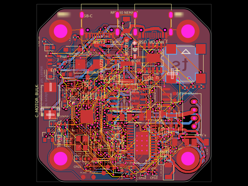 Similar packageimrishabh18/rp2040-motor-controllerA four-layer RP2040-based NEMA17 stepper controller with USB-C power/data, CH224K USB-PD negotiation, DRV8825 dual H-bridge drive, current/temperature telemetry, RGB status LED, buzzer alarm, QSPI flash, and optional AS5600 encoder.
 Discover something newMustafaMulla29/wireless-mouse-pcbA hardware component library defining footprints and 3D models for a 3.3 V regulator, RF antenna, switches, connectors, battery charger, and nRF52810 Bluetooth microcontroller.