abse/gameboy-advance
Validates and exports a four-layer Game Boy–style PCB assembly with RP2350 MCU, 32MB flash, USB-C, LCD and speaker connectors, battery buck-boost power, buttons, and verified routing, connectivity, clearances, CAD models, and physical DRC.
- Version
- 0.0.39
- License
- unset
- Stars
- 0
AA_BATTERY_ASSEMBLY.md
> Routing update: default four-AA board is now through-via-only and freshly validated. See ../through-via-reroute/RESULT.md. Three-AA source remains available but has not been freshly rebuilt after this reroute; older validation claims below refer to the previous PCB.

# AA battery assembly options

This routed PCB supports a series pack of three or four ordinary 1.5 V alkaline AA cells. Choose the population of `R_BAT_EN_BOTTOM` to match the holder during assembly. Cell count is not detected automatically.

| Pack | R_BAT_EN_TOP | R_BAT_EN_BOTTOM | Lower resistor JLCPCB | Typical startup | Typical shutdown |
|---|---:|---:|---|---:|---:|
| 3 × AA, optional assembly | 390 kΩ | 130 kΩ | C22795 | 3.20 V | 2.80 V |
| 4 × AA, default | 390 kΩ | 100 kΩ | C25803 | 3.92 V | 3.43 V |

Both lower resistors use the same verified 0603 footprint. The same PCB and copper routing serve both assemblies; their BOM quantities differ. The four-AA variant retains the preceding board's resistor population. The three-AA variant changes only the lower enable-divider resistor.

The TPS63070 converter requires at least 3.0 V for a cold start and is specified down to 2.0 V after startup. Thresholds in the table are typical values. IC threshold, resistor tolerance, control-pin leakage, contact losses and cell condition affect the actual startup and shutdown voltages.

Use the existing J_BAT two-pin connector: pin 1 is positive, pin 2 is ground. Cells are wired in series. Use the sourced four-AA holder and actual cable assembly specified in the assembly guide; the holder mounts to the rear shell with inserts. Reverse protection, fuse, USB source isolation and the regulated approximately 5V /3.234V rails remain in place. USB does not recharge the AA pack.

Four AA cells are the default. The 100 kΩ resistor (C25803) is fitted during board assembly; the user does not need to solder a resistor to use the default pack. Four cells offer longer expected runtime than three under comparable operating conditions.

Build the default four-AA assembly with `npm run build` or `npm run build:4aa`; build the optional three-AA assembly with `npm run build:3aa`. Outputs are `dist/index` and `dist/index-3aa`, respectively, each with its own `assembly-bom.csv` and validation report. The optional three-AA entry is `index-3aa.circuit.tsx`. Changing to three cells requires its corresponding resistor population during assembly.

Both normal native builds pass with four layers and zero physical DRC, Gerber shorts or PCB trace-style findings. Existing 9 length findings and 23 width warnings remain separately reported, with no new or worsened findings. Supporting these packs does not establish a measured 10–15-hour runtime; brightness, firmware load, display, card and speaker remain relevant.

The local JST-SH speaker revision uses CMS-23558N-L152B and connector C160388. See [speaker assembly notes](./SPEAKER_ASSEMBLY.md), including the required 1 W audio output limit.
Related Packages
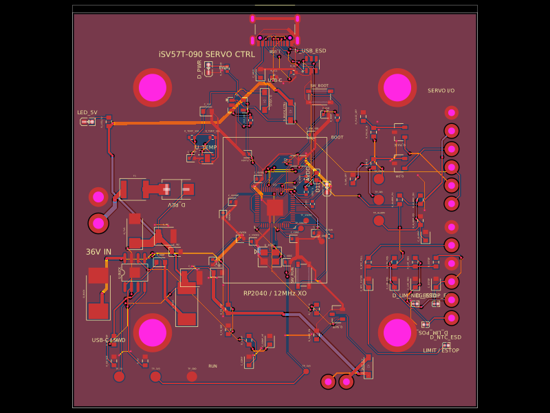 More from this authorabse/isv57t090-motion-controllerA 36 V-powered RP2040 motion-controller PCB that regulates 5 V, drives isolated STEP/DIR servo inputs, monitors alarms, temperature, limits and E-stop signals, and provides protected safety/field connectors.
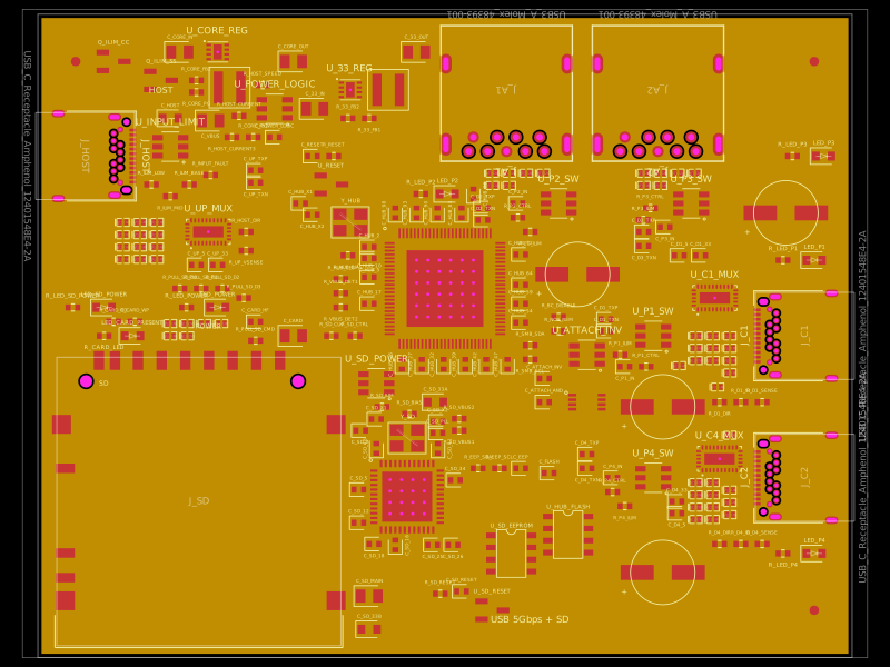 Similar packagegokul/usb3-sd-hubEngineering draft: four-layer, computer-powered USB 3 hub with one USB-C host socket, two USB-C and two USB-A accessory sockets, and a full-size SD slot. Board and three schematic previews are available. Routing and production checks are incomplete; not fabrication ready.
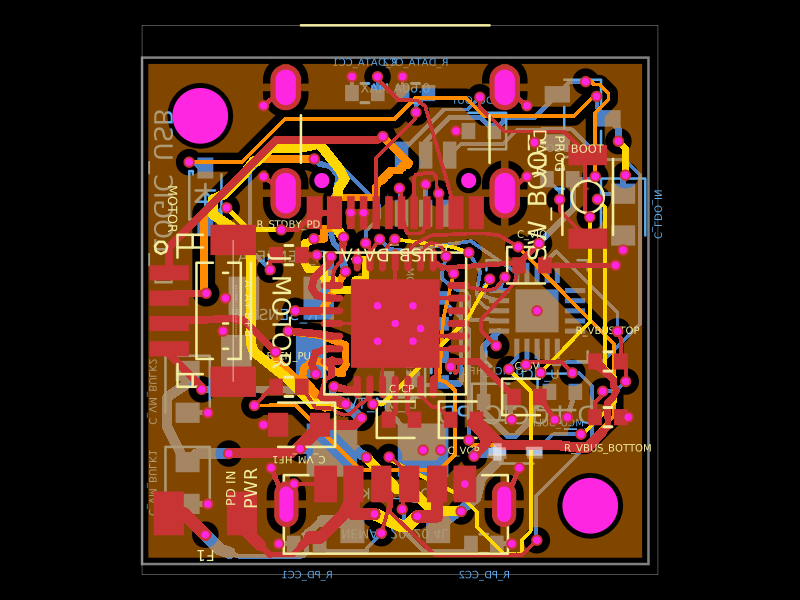 Discover something newShiboSoftwareDev/nema8-20mm-usbc-pd-controllerA 20×20 mm four-layer USB‑C PD stepper motor controller PCB using a CH32X035 MCU, TMC2209 driver, protected power inputs, USB data/boot interface, 3.3 V regulation, ESD/TVS protection, current-sense circuitry, and NEMA‑8 motor outputs.