ShiboSoftwareDev/solar-battery-charger
This code defines various surface-mount and through-hole electronic components (like diodes, voltage regulators, and ICs) with detailed footprints, 3D models, and pin configurations for PCB design.
- Version
- 1.0.2
- License
- unset
- Stars
- 0
README.md
This is a solar battery charger and power module. In this tscircuit version, the core circuit is in index.circuit.tsx:109.

  What It Does

  - Takes power from a solar panel on SLPWR1 / “Solar Panel”.
  - Uses a BQ24650 solar buck charger controller to charge a battery using MPPT-style input voltage regulation. TI describes this
    part as a standalone 1-6 cell buck charger with solar input and programmable MPPT; it supports 5-28 V solar input and
    resistor-set charge voltage/current.
  - The resistor values in this design set roughly:
      - Solar input regulation / MPPT point: about 17.8 V, so it expects a panel whose useful operating voltage is around 18 V.
      - Main charge voltage: about 12.6 V, consistent with a 3-cell Li-ion/LiPo pack.
      - Charge current: likely about 2 A, assuming the usual BQ24650 sense formula with RSR1 = 0.02 ohm.
  - Provides a regulated VOUT rail using an LT1129-3.3 LDO, so VOUT is intended to be a switched/controlled 3.3 V output.
  - Includes an STC3117 fuel-gauge/monitor IC connected to SDA, SCL, and ALM so a host MCU can read battery status and receive
    low-battery/fault alarms.
  - Includes an MCP73113 single-cell Li-ion charger section tied to BATD, so the reference appears to include support for a small
    single-cell/backup battery path as well.

  How To Use It

  - Connect the solar panel to the board’s Solar Panel connector, SLPWR1.
      - pin1 = VCC
      - pin2 = GND
  - Connect the battery pack to the Battery Connector, SLPWR2.
      - In this local design, it is wired as BATD and CS, not simply BAT+ and GND, so verify the original reference schematic
        before powering hardware.
  - Use the edge pads:
      - VIN: raw external input pad in this layout.
      - GND: common ground.
      - VOUT: regulated output, apparently 3.3 V.
      - ON_OFF: controls the LT1129 shutdown pin, enabling/disabling VOUT.
      - nCE: charger enable/control input.
      - SDA / SCL: I2C lines for the STC3117 battery monitor.
      - ALM: alarm output from the STC3117.

  Devices Required

  - An assembled PCB for this design.
  - A solar panel suitable for the BQ24650 input, practically around 18 V Vmp / 21 V nominal open-circuit class, and within the
    BQ24650’s 5-28 V operating range.
  - A compatible rechargeable battery pack. Based on the divider values, the main charger target is about 12.6 V, so this looks
    like a 3S Li-ion/LiPo battery pack. Use a protected pack or add a proper BMS.
  - A load that runs from the VOUT rail, likely 3.3 V, within the LT1129 current/thermal limits.
  - Optional host MCU if you want to use SDA, SCL, ALM, ON_OFF, and nCE.

  Important caveat: before building or applying power, compare this tscircuit port against the original GitHub reference
  schematic. The local net names around BATTERY, BATD, CS, and VIN_RAW are easy to misuse, and battery charger mistakes can
  damage cells or create a fire risk.

  Sources: local circuit files, the referenced GitHub project, TI BQ24650 product page, Microchip MCP73113 page, ST STC3117 page,
  and Analog Devices LT1129 page.
Related Packages
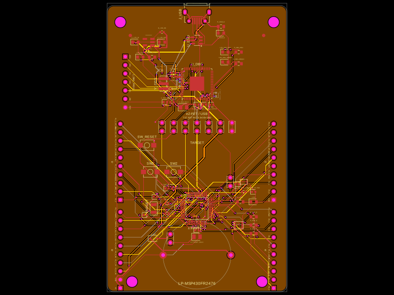 More from this authorShiboSoftwareDev/lp-msp430fr2476This design implements a microcontroller-based development board featuring an MSP430FR2476 target MCU with associated power regulation, USB host interface with ESD protection, multiple headers for peripherals and BoosterPacks, and integrated status LEDs and sensors.
 Similar packagemohan-bee/speakerThis code defines configurable 3D models and PCB footprints for various electronic components, including a battery charger IC, a dual Hall sensor, a dual power switch, and a voltage regulator, with detailed pinouts, footprints, and CAD models for schematic and physical design.