ShiboSoftwareDev/mspm0g3507-gameboy-handheld
An AO3400A N-channel MOSFET for power switching and an AP2112K-3.3TRG1 LDO regulator providing a regulated 3.3 V output, both in compact SMD packages.
- Version
- 1.2.1
- License
- unset
- Stars
- 0
README.md
# MSPM0G3507 Game Boy-style handheld

A fabrication-ready, four-layer handheld game board built around TI's 80 MHz Arm Cortex-M0+ MSPM0G3507. The 72 mm × 112 mm PCB combines protected single-cell LiPo operation and charging, USB-C power and ROM-bootloader programming, a selected 2.4-inch IPS display interface, an eight-button Game Boy-style control layout, status LEDs, an external amplified-audio connector, and production SWD test pads.

The board is intended for retro games and small embedded demos written for the MSPM0G3507. It is not electrically compatible with Nintendo cartridges or accessories.

## Battery and power

Connect a **protected 1S LiPo pack** (3.7 V nominal, 4.2 V maximum) to the three-pin JST-PH connector at the lower-left edge:

| Battery pin | Function |
|---:|---|
| 1 | Cell positive |
| 2 | 10 kΩ NTC temperature sense |
| 3 | Cell negative / ground |

Verify the pack lead order before insertion; LiPo connector polarity is not universally standardized. Do not use an unprotected cell or a two-wire pack without the required 10 kΩ NTC connection.

The BQ24075 power-path charger accepts USB-C 5 V, limits USB input current to about 500 mA, and charges at about 270 mA with the fitted 3.3 kΩ ISET resistor. Its system output feeds a TPS63031 buck-boost regulator for the stable 3.3 V logic rail and a TPS61240 boost regulator for the display's 5 V backlight rail. The side switch enables both regulators; USB charging remains available with the switch off. Six fitted 1206 zero-ohm links join the USB, power, MCU, controls, display, and user-I/O ground domains at an explicit star connection.

## Handheld controls

All game buttons are active-low. Firmware must enable the MSPM0's internal pull-up resistors.

| Control | MCU pin | Net |
|---|---:|---|
| D-pad Up | PA2 | `BTN_UP` |
| D-pad Down | PA3 | `BTN_DOWN` |
| D-pad Left | PA4 | `BTN_LEFT` |
| D-pad Right | PA5 | `BTN_RIGHT` |
| A | PA6 | `BTN_A` |
| B | PA7 | `BTN_B` |
| Start | PA12 | `BTN_START` |
| Select | PA13 | `BTN_SELECT` |

The front-panel footprint positions form an 18 mm-pitch D-pad cross, angled A/B cluster, and centered Start/Select pair. Each control now uses a 5.2 mm × 5.2 mm JLCPCB-assembled tactile switch (`C10852`) with a marked 8 mm enclosure-plunger area. The display window and control names are outlined on the PCB silkscreen for enclosure alignment.

## Display and audio

The display interface is designed for BuyDisplay's `ER-TFT024IPS-3`: a 2.4-inch 240 × 320 IPS TFT using the ST7789 controller and a 50-contact, 0.5 mm-pitch FPC. The PCB carries a JLCPCB-assembled top-contact ZIF connector (`C2911826`). The display itself must be purchased separately from BuyDisplay and inserted during final assembly.

| FPC pin | Signal | MCU pin |
|---:|---|---:|
| 10 | RESET_N | PA9 |
| 34 | SDI / MOSI | PB8 |
| 36 | D/C | PA8 |
| 37 | SCL / SCK | PB9 |
| 38 | CS_N | PB15 |
| 40, 41 | VDDI, 3.3 V | — |
| 42 | VCI, 3.3 V | — |
| 43, 48–50 | GND | — |

Mode pins IM3..IM0 are strapped `0,1,1,0` for four-wire SPI mode. The four LED cathodes each have a 100 Ω current-limiting resistor and are PWM-switched through an AO3400A from PA16; the LED anode is fed from the regulated 5 V backlight boost through a local zero-ohm link, so the display works from either battery or USB power.

The four-pin JST-SH audio connector exposes GND, 3V3, `AUDIO_PWM` on PA14, and `AUDIO_ENABLE` on PA15. It is for a 3.3 V amplified-audio module; do not connect a speaker directly to the MCU pin.

## USB programming and debug

The USB-C connector feeds the BQ24075 charger/power path and a protected CH340C USB-to-UART bridge. The system switch must be on for programming. CH340 TXD connects through 1 kΩ to PA11/BSL_RX, and PA10/BSL_TX connects through 1 kΩ to CH340 RXD.

To invoke the factory ROM bootloader:

1. Hold **BOOT**.
2. Press and release **RESET**.
3. Release **BOOT**.
4. Program the device with TI's MSPM0 BSL host software over the CH340 serial port.

Five 1.8 mm service pads expose GND, 3V3, SWDIO, SWCLK, and RESET for bed-of-nails programming and recovery.

BOOT and RESET are grouped beside the MCU in a marked service-pinhole area so the enclosure can keep them recessed and away from the game controls.

## Fabrication

- Four copper layers, all assembly parts on the top side.
- 0.30 mm through-via drills with 0.45 mm pads.
- Four isolated 2.7 mm mounting holes and three SMT fiducials.
- Explicit manufacturer and JLCPCB/LCSC identifiers for all 69 assembly placements.
- USB-C shield slots and locating holes are included in the drill output.
- Five service test pads are intentionally excluded from the BOM.
- The design uses `tscircuit` 0.0.2572.
- The schematic is split into eight focused sheets: USB/programming, battery/charger, regulated power rails, ground-star links, MCU/debug, display, controls, and audio/indicators.

Generate and audit the release files with:

```sh
bun run typecheck
bun run build
bunx tsci check netlist index.circuit.tsx
bunx tsci check pin_specification index.circuit.tsx
bunx tsci check placement index.circuit.tsx
bunx tsci check source index.circuit.tsx
bunx tsci check shorts index.circuit.tsx
bun run audit:fabrication
bun run release:artifacts
bun run audit:gerbers
```

The manufacturing bundle is written to `outputs/` and includes Gerbers, BOM, CPL, PCB, schematic, and assembly views. The custom fabrication audit verifies the LiPo connector and charger, both switching regulators, ground-domain links, control matrix, display and audio pinouts, boot/debug nets, switching-node and VCORE routes, board mechanics, courtyards, paste layers, and built-in tscircuit netlist/pin/placement/routing checks.

Part availability changes over time. Run `bun run check:jlc-stock` immediately before ordering, then build a small first-article batch and validate USB enumeration, bootloader entry, all eight controls, display timing/backlight, audio-module behavior, and sustained 3.3 V rail load before volume production.

Part inventory is live data; the latest exact-match stock result is printed by `bun run check:jlc-stock` and should be re-run immediately before ordering.
Related Packages
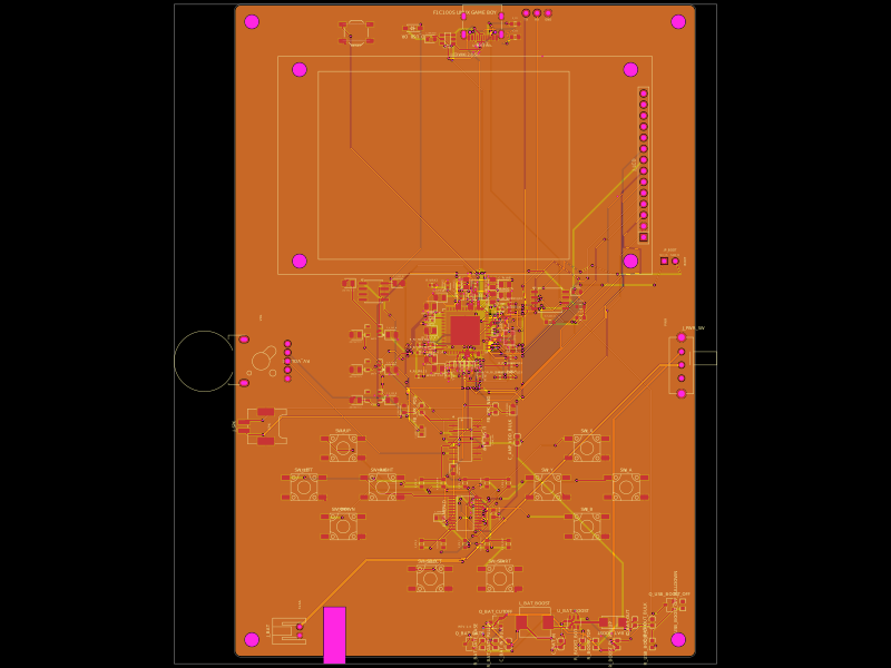 More from this authorShiboSoftwareDev/f1c100s-linux-gameboyRestores PCB assembly metadata by assigning part numbers, managing 3D CAD models and orientations, removing test-point bodies, and validating top-side SMT solder-paste features.
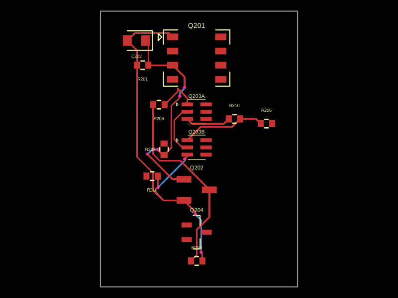 Similar packageastrimid/ec_driven_dc_isolationThis code models a power control circuit featuring NPN and P-channel MOSFETs, resistors, and capacitors, including a dual N-channel MOSFET package, to manage power paths and switching functions on a hardware PCB.
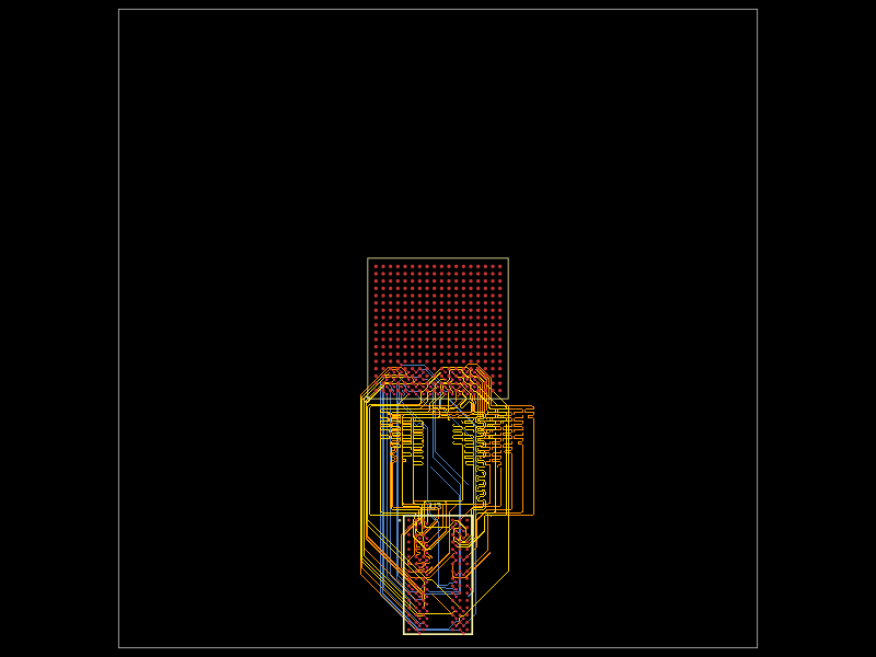 Discover something newseveibar/am3352-ram-dogbone-and-single-layer-route-testAM3352BZCZ100 processor connected to a W631GG6MB-12 DDR3 memory chip through a routed, length-matched 16-bit DDR interface with clock/data-strobe pairs and control/address signals.