ShiboSoftwareDev/linux-gameboy-advance
Restores PCB assembly metadata by assigning part numbers and 3D CAD models, removing test-point bodies, and validating top-side SMT solder-paste features without altering copper or pads.
- Version
- 1.0.17
- License
- unset
- Stars
- 0
scripts/generate-screen-model.mjs
import { writeFile } from "node:fs/promises"
import { dirname, resolve } from "node:path"
import { fileURLToPath } from "node:url"
import jscad from "@jscad/modeling"
import { convertJscadModelToGltf } from "jscad-to-gltf"

const { primitives, transforms } = jscad
const { cuboid, roundedCuboid } = primitives
const { rotateX, translate } = transforms

// ER-TFT035IPS-6 capacitive-touch configuration, modeled from the
// manufacturer's outline drawing. The origin is the center of the mating edge
// of the 50-pin FPC so tscircuit can anchor the assembly directly to J_LCD.
const PANEL = {
  width: 55.5,
  height: 84.96,
  thickness: 2.5,
  activeWidth: 48.96,
  activeHeight: 73.44,
  flexWidth: 25.5,
  flexThickness: 0.18,
  contactPitch: 0.5,
  contactWidth: 0.32,
  contactCount: 50,
  stiffenerLength: 5,
  stiffenerThickness: 0.3,
}

const COLORS = {
  active: [0.018, 0.12, 0.17],
  bezel: [0.035, 0.04, 0.05],
  backlightFrame: [0.63, 0.66, 0.68],
  reflector: [0.82, 0.84, 0.85],
  flex: [0.86, 0.47, 0.075],
  flexTrace: [0.48, 0.19, 0.035],
  copper: [0.83, 0.49, 0.12],
  stiffener: [0.16, 0.32, 0.65],
  driver: [0.035, 0.035, 0.04],
}

const geometries = []

const add = (geom, color) => geometries.push({ geom, color })

const box = ({ size, center, color, radius = 0 }) => {
  const shape = radius > 0
    ? roundedCuboid({ size, center, roundRadius: radius, segments: 16 })
    : cuboid({ size, center })
  add(shape, color)
}

const stripBetween = ({ start, end, width, thickness, color }) => {
  const dy = end[1] - start[1]
  const dz = end[2] - start[2]
  const length = Math.hypot(dy, dz)
  const center = [
    (start[0] + end[0]) / 2,
    (start[1] + end[1]) / 2,
    (start[2] + end[2]) / 2,
  ]
  const angle = Math.atan2(dz, dy)
  const strip = cuboid({ size: [width, length, thickness] })
  add(translate(center, rotateX(angle, strip)), color)
}

// The panel is mounted in front of the component side, leaving 7 mm from the
// PCB surface to the metal backlight frame. Its portrait geometry is rotated
// into landscape by the real connector insertion direction in index.circuit.
const panelNearEdgeY = 1
const panelCenterY = panelNearEdgeY + PANEL.height / 2
const panelBackZ = 7

box({
  size: [54.5, 83, 1.55],
  center: [0, panelCenterY, panelBackZ + 0.775],
  color: COLORS.backlightFrame,
  radius: 0.18,
})
box({
  size: [53.7, 82.2, 0.08],
  center: [0, panelCenterY, panelBackZ - 0.05],
  color: COLORS.reflector,
})
box({
  size: [PANEL.width, PANEL.height, 0.78],
  center: [0, panelCenterY, panelBackZ + 1.94],
  color: COLORS.bezel,
  radius: 0.14,
})
box({
  size: [PANEL.activeWidth, PANEL.activeHeight, 0.07],
  center: [0, panelCenterY, panelBackZ + PANEL.thickness + 0.025],
  color: COLORS.active,
  radius: 0.02,
})

// FPC: a low section enters the bottom-contact ZIF, then rises under the
// display and lies against the display back. This represents the real folded
// installation instead of shortening the cable to an artificial 1 mm tab.
const flexPath = [
  [0, 0, 0.32],
  [0, 8, 0.32],
  [0, 10, 1.25],
  [0, 12, 3.65],
  [0, 14, panelBackZ - 0.28],
  [0, 30, panelBackZ - 0.28],
]

for (let i = 0; i < flexPath.length - 1; i += 1) {
  stripBetween({
    start: flexPath[i],
    end: flexPath[i + 1],
    width: PANEL.flexWidth,
    thickness: PANEL.flexThickness,
    color: COLORS.flex,
  })
}

// Copper fingers are on the lower face for the bottom-contact J_LCD socket.
for (let i = 0; i < PANEL.contactCount; i += 1) {
  const x = (i - (PANEL.contactCount - 1) / 2) * PANEL.contactPitch
  box({
    size: [PANEL.contactWidth, PANEL.stiffenerLength, 0.035],
    center: [x, PANEL.stiffenerLength / 2, 0.2125],
    color: COLORS.copper,
  })
  box({
    size: [0.18, 17.5, 0.025],
    center: [x, 21.25, panelBackZ - 0.16],
    color: COLORS.flexTrace,
  })
}

box({
  size: [PANEL.flexWidth, PANEL.stiffenerLength, PANEL.stiffenerThickness],
  center: [0, PANEL.stiffenerLength / 2, 0.56],
  color: COLORS.stiffener,
})

// The bonded driver area and strain-relief strip remain visible from the rear.
box({
  size: [20.5, 2.2, 0.42],
  center: [0, 28.2, panelBackZ - 0.52],
  color: COLORS.driver,
  radius: 0.08,
})
box({
  size: [PANEL.flexWidth, 1.1, 0.32],
  center: [0, 30, panelBackZ - 0.44],
  color: COLORS.flex,
})

const result = await convertJscadModelToGltf(
  { geometries },
  {
    format: "glb",
    meshName: "ER-TFT035IPS-6-realistic-assembly",
    axisTransform: "none",
  },
)

const scriptDir = dirname(fileURLToPath(import.meta.url))
const outputPath = resolve(scriptDir, "../assets/er-tft035ips-6-realistic.glb")
await writeFile(outputPath, new Uint8Array(result.data))
console.log(`wrote ${outputPath} (${result.byteLength} bytes)`)
Related Packages
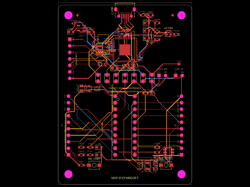 More from this authorShiboSoftwareDev/msp-exp430g2etThis circuit integrates a 4MHz crystal resonator, various resistors and capacitors for power management and filtering, a microcontroller (MSP430F5528), and multiple connectors and test points to enable USB communication, programming, and system monitoring with shielding and grounding.
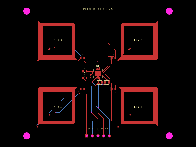 Similar packagehrithik18k/metal-touch-panelA PCB autorouting wrapper that corrects footprint-trace obstacle dimensions, solves routes with a preloaded trace-graph solver, and reports completed traces or routing errors.
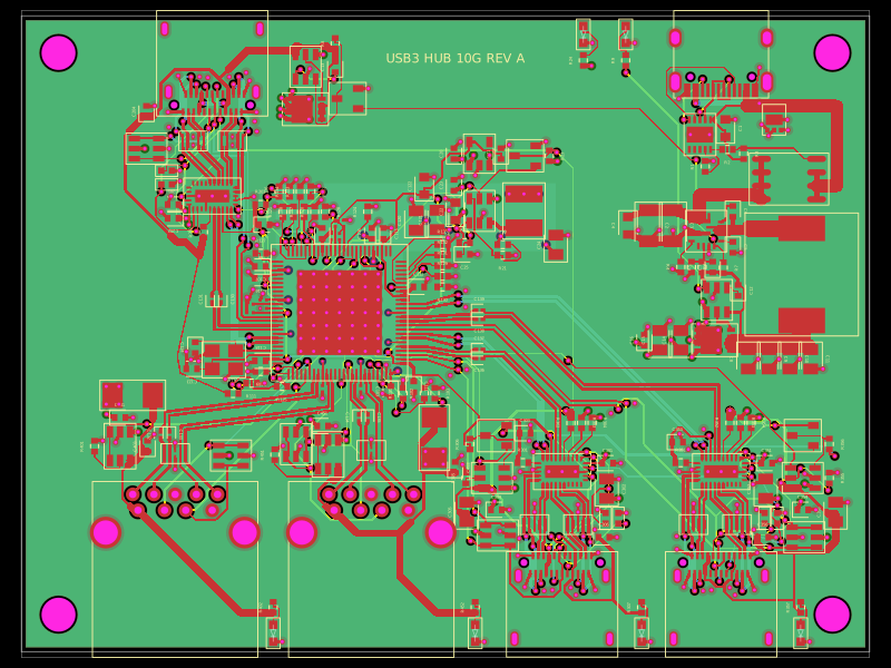 Discover something newpixalynx/usb3-hub-10gA USB 3.2 Gen 2 six-port hub board with USB-C PD power input, regulated 5 V/3.3 V/1.15 V rails, one upstream and four protected downstream USB-A/USB-C ports, SuperSpeed muxes, ESD protection, and controlled port power.