ShiboSoftwareDev/linux-gameboy-advance
A multilayer PCB carrier board routing the MCU, USB‑C, battery/AA power selector and TPS63020 regulator, LCD/SD interfaces, UART/I²C/SPI service headers, controls, audio/status LEDs, and backlight with reviewed traces and vias.
- Version
- 1.0.125
- License
- unset
- Stars
- 0
schematic/SchematicSheets.tsx
/**
 * Functional A4 drawings for the handheld.
 *
 * Leaving sheetWidth/sheetHeight unset deliberately selects tscircuit's
 * standard 297 x 210 mm A4 frame and lets each frame center on its authored
 * contents. Component coordinates are kept compact enough that traces and
 * labels remain inside the usable drawing area.
 */
export const SchematicSheets = () => <>
  <schematicsheet name="soc_interfaces" displayName="1 — F1C100S interfaces"
    sheetIndex={1} sheetSize="A4">
    <schematictext text="F1C100S functional units • RGB • storage • GPIO • audio • USB"
      schX={0} schY={-9} fontSize={0.4} />
  </schematicsheet>

  <schematicsheet name="soc_power" displayName="2 — F1C100S power and decoupling"
    sheetIndex={2} sheetSize="A4">
    <schematictext text="Local decoupling grouped by 3V3 / 2V5 / 1V2 / 2V8 rail"
      schX={1} schY={-5.5} fontSize={0.4} />
  </schematicsheet>

  <schematicsheet name="soc_support" displayName="3 — F1C100S clock and support"
    sheetIndex={3} sheetSize="A4">
    <schematictext text="24 MHz clock • reset • analog references • storage and I²C pull-ups"
      schX={0} schY={-9} fontSize={0.4} />
  </schematicsheet>

  <schematicsheet name="display" displayName="4 — RGB display interface"
    sheetIndex={4} sheetSize="A4">
    <schematictext text="RGB666 panel • SPI1 init • 3V3 logic • I²C touch"
      schX={0} schY={-5} fontSize={0.4} />
  </schematicsheet>

  <schematicsheet name="storage" displayName="5 — Boot and removable storage"
    sheetIndex={5} sheetSize="A4">
    <schematictext text="4-bit microSD • W25Q128 recovery flash • boot CS solder bridge"
      schX={0} schY={-5} fontSize={0.4} />
  </schematicsheet>

  <schematicsheet name="controls_service" displayName="6 — Controls and service interfaces"
    sheetIndex={6} sheetSize="A4">
    <schematictext text="PCF8575 active-low controls • UART RX–GND–TX • I²C • shared SPI1"
      schX={0} schY={-11} fontSize={0.4} />
  </schematicsheet>

  <schematicsheet name="usb_power" displayName="7 — USB-C and primary power"
    sheetIndex={7} sheetSize="A4">
    <schematictext text="One USB-C supplies USB2/FEL data and default 5 V sink power"
      schX={0} schY={-8} fontSize={0.4} />
    <schematictext text="2×AA and USB feed a TPS63020 buck-boost through automatic source selection"
      schX={0} schY={-8.8} fontSize={0.4} />
  </schematicsheet>

  <schematicsheet name="secondary_rails" displayName="8 — Secondary SoC rails"
    sheetIndex={8} sheetSize="A4">
    <schematictext text="3V3 → 2V5 DRAM • 1V2 core • 2V8 analog"
      schX={0} schY={-4} fontSize={0.4} />
  </schematicsheet>

  <schematicsheet name="audio" displayName="9 — Audio output"
    sheetIndex={9} sheetSize="A4">
    <schematictext text="PAM8403 mono BTL • volume • EMI filter • 4–8 Ω speaker"
      schX={0} schY={-5} fontSize={0.4} />
  </schematicsheet>

  <schematicsheet name="backlight" displayName="10 — LCD backlight regulator"
    sheetIndex={10} sheetSize="A4">
    <schematictext text="AP3031 boost • 100 mA LED current • 2 Ω sense"
      schX={0} schY={-5} fontSize={0.4} />
  </schematicsheet>

  <schematicsheet name="status" displayName="11 — RGB status indicator"
    sheetIndex={11} sheetSize="A4">
    <schematictext text="3V3 common-anode RGB • active-low PCF8575 P14 / P15 / P16 • reset default off"
      schX={0} schY={-2} fontSize={0.4} />
  </schematicsheet>
</>
Related Packages
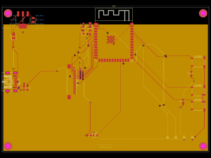 More from this authorShiboSoftwareDev/muse-reterminal-e1001-replacementA four-layer ESP32-S3 e-paper carrier board with USB-C power, AMS1117 3.3V regulation, 24-pin FFC interface, reset/boot and user buttons, status LED, decoupling passives, test points, mounting holes, and ground/power planes.
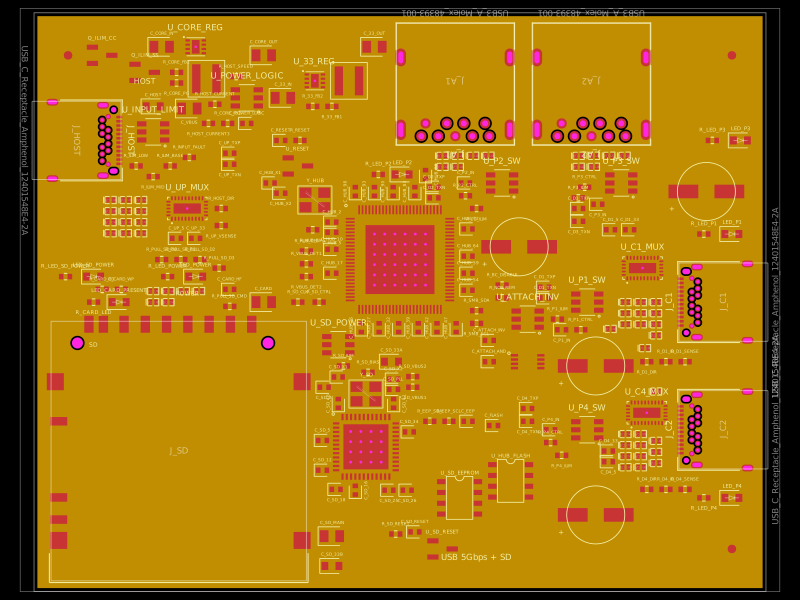 Similar packagegokul/usb3-sd-hubEngineering draft: four-layer, computer-powered USB 3 hub with one USB-C host socket, two USB-C and two USB-A accessory sockets, and a full-size SD slot. Board and three schematic previews are available. Routing and production checks are incomplete; not fabrication ready.
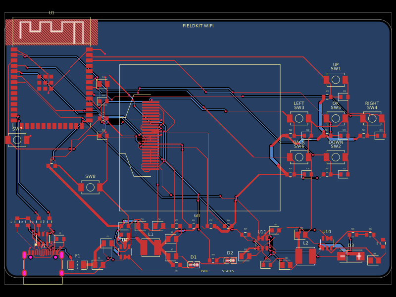 Discover something newgokul/fieldkit-usbUSB-C-powered ESP32-S3 Wi-Fi/Bluetooth handheld with an SMD 128x32 OLED, six navigation buttons, USB-C power/data, complete checked routing, and four native schematic sheets.