ShiboSoftwareDev/linux-gameboy-advance
Multilayer PCB carrier board integrating USB‑C, battery charging/power management, buck‑boost regulation, MCU/SoC, LCD/SD interfaces, audio controls, status LEDs, backlight, and UART/I²C/SPI service connectors with reviewed multilayer copper and vias.
- Version
- 1.0.134
- License
- unset
- Stars
- 0
mechanical/ENCLOSURE_AUDIT.md
# Enclosure design audit

Datum: PCB centre, PCB mid-plane Z=0, dimensions in millimetres. This audit is
checked against the evaluated assembly GLB, not only the TSX source. The
release gate is `bun run assembly:3d`; it rejects missing models,
multi-body printed parts and the measured stack failures listed below.

## Exterior and ergonomics

| Feature | Design decision | Nominal check |
| --- | --- | ---: |
| Body | Symmetric board-derived outline with 1.6 mm rear floor, 1.4 mm walls and 1.6 mm lid | 148.9 x 88.67 x 30.6 |
| Shell location | Four M3 closure stacks plus four broad internal lid registration tongues | 0.20-0.25 cavity clearance |
| LCD | Landscape OEM rigid geometry, top edge flush with the PCB, FPC/connector at right | panel 84.96 x 56.54 |
| Face keys | Captive rear flanges, individual stem sockets, switch-spring return | 3.65 proud; 0.30 radial guide; zero nominal stem gap; physical free-play qualification required |
| Start/Select | Central pair below the LCD, outside both primary hand clusters | (-14,-26), (1,-26) |
| D-pad | Rear-flanged rocking cross with spherical foot and narrow guides | 1.0 mm pivot pad; zero foot gap; 6 mm pockets; 2.5-degree rocking sweep |
| L/R | Captive sliding paddles with matched radiused guides and vertical-overhang retainers | 0.30 lateral/vertical; 0.40 retainer overhang; 0.40 usable stroke |
| Power | Left straight wall, guarded against palm presses; housing stays inside PCB | 4.50 actuator protrusion; 0.50 body inset |
| Volume | Pin-aligned supplier model, concentric collar, removable lid skirt for access | about 0.97 mm exterior reach; 0.40 mm radial and 0.35 mm axial aperture clearance |
| microSD | Card mouth flush with the right PCB edge, protected by the case wall tunnel | no PCB cutout or overhang |
| USB-C | One lower-edge connector for 5 V power and USB2/FEL data | opening centred on real connector model |
| Speaker | Front-lid grille over a sealed Same Sky CMS-2004-18SP, real terminal pads and snap strain relief | 20 x 4.2 driver; 19 x 2 mm holes; 19.0% open area |
| Battery access | Flush stepped rear door with thumb dimple, insertion tongue and integral cantilever latch | 0.45 lateral / 0.10 axial clearance |

The guide gaps are deliberate running clearances. Removing them from the model
would describe fused printed parts, not a functioning mechanism.

## Structural and internal load paths

### Shell and PCB

Four recessed ISO 7045 M3 x 24 pan-head screws enter from the rear, seat flush in the base,
pass through the base towers and PCB, and engage heat-set inserts in lid
pillars. A 0.5 mm nylon washer lies between each PCB annulus and pillar. The
evaluated model uses 5.7 x 4.6 mm M3 inserts and validates the screw, insert and
washer envelopes directly from the exported GLB.

The lid has four broad 0.8 mm-wide, 1.8 mm-deep internal registration tongues. They are deliberately not a
continuous perimeter tongue: a continuous top key would intersect the LCD,
while continuous side keys would cross controls and edge connectors.

### LCD

Four independent M2.5 PCB holes carry a single connected PA12 carrier. Its
2.4 mm arms and 5-7 mm perimeter rails have a common Z=8.20 bearing plane and support the LCD
inactive border through a 0.5 mm foam gasket with 0.10 mm modeled compression.
The front shell seals the display through a separate 0.5 mm gasket with 0.05
mm total modeled compression. The two bearing rails connect through routed side
load paths, leaving the centre component field, active area, right-side FPC fold
and connector corridor open. The left structural
rail is split above and below the D-pad's `SW_RIGHT` body. Export compares the
evaluated 3D envelope of every fitted PCB component against every carrier boss
and rail, and separately checks the carrier against both enclosure shells.
Export fails if either gasket is
embedded in its support or floats short of the adjacent surface.

### Battery bay

The bay uses one protected two-wire Jauch LP906090JH 1S 6000 mAh pouch with a
separately bonded 10 kΩ NTC.
The modeled 93.5 x 60.5 x 9.9 mm cycled envelope has 1.0 mm clearance per X/Y
side inside a 95.5 x 62.5 x 10.9 mm pocket. A compressed 1.25 mm rear pad and
four 4 mm PCB-side pads support and electrically isolate the pack while leaving
4.2 mm between its cycled envelope and the PCB.

The red, black and NTC conductors, the device-side harness and a locking
three-circuit JST ZOM service pair (ZOMP-03V-A-S and ZOMR-03VF-A-S) are present
in the evaluated assembly. Each is checked against the shells, PCB, LCD
carrier, pouch, door and all four M3 service screws. The door has a 0.9 mm
perimeter flange and a 1.8 mm reinforced centre.
Its inner registration tongue is a perimeter ring, not a solid plate, so it
does not press on the pouch face.
The door's latch is part of the door itself: a 16.0 x 1.2 mm cantilever
terminates in a positive hook, while parallel relief slots provide the required
0.55 mm compliance without a separate loose part. The analytical surface-strain
gate is 1.0%; the current geometry evaluates at approximately 0.526%. The door
is installed tongue-first and its rigid-body closing sweep is collision-checked
at 4, 6 and 8 degrees.

### Speaker

The manufacturer-dimensioned 20 x 4.2 mm CMS-2004-18SP driver sits in a front-lid cradle
with 0.35 mm radial print clearance. Its terminal carrier and two contact pads
are represented in the assembly, and both leads begin at those pads before
passing through the integrated two-channel snap strain relief.
A closed-cell ring seals to the front lid with 0.10 mm compression. A
two-screw retainer applies a separate 0.10 mm preload. J_SPK and its short lead
stay internal; there is no unnecessary exterior connector hole. The front-firing
grille remains open when the handheld is held or placed on a table.

## Exported-geometry gates

- All 15 printed objects must evaluate to exactly one connected triangle body.
- All fitted component bodies, the PCB and every required mechanical part
  must be present in the assembly GLB.
- Face keys must align to the real switch actuators with zero nominal rest gap
  and at least 0.25 mm socket radial clearance. The actual exported socket
  ceiling is measured; an authored plane alone is not accepted as proof.
- Both shoulder keys must align to their real TS6695 actuator models, retain
  0.28-0.35 mm guide clearance, overhang the guide by at least 0.35 mm, keep
  the blind pocket closed at the finger face, and provide at least 0.40 mm
  usable switch stroke after the rest gap. Exact shell intersections are run
  at rest and at the full 0.65 mm inward sweep.
- PCB, carrier, door, speaker retainer, D-pad, six face caps and both shoulder
  paddles are exact-mesh checked against their mating shell(s); face controls
  are checked at rest and full nominal stroke.
- The direct-drive volume collar must stay within 0.03 mm of the real supplier
  wheel centre, project 0.90-1.10 mm beyond the actual shell profile, retain 0.38-0.42
  mm radial aperture clearance, at least 0.30 mm axial clearance, at least 0.12
  mm PCB clearance, at least 0.5 mm to the adjacent washer and 1.1 mm polymer
  around the insert after local pillar relief. The collar is exact-mesh checked
  through an installation lift with the lid removed and against both shells, PCB and nearby
  M3 hardware; its deliberate grip-rib engagement with the supplier wheel is
  checked as a separate 0.13-0.18 mm fit condition.
- The M3 closure stack, battery-to-PCB gap, door-to-cell gap and speaker gasket
  compression are measured from exported meshes and are release-blocking.
- All three battery conductors and both speaker leads are exact-mesh checked
  against the pouch, battery door, shells, PCB, LCD carrier and service screws.
- The installed LCD flex path must retain at least 2.0 mm bend radius and at
  least 10 times the modeled 0.20 mm flex-stack thickness.
- The battery isolation pads must contact both adjacent faces without modeled
  penetration or float; the
  speaker grille must retain 15% open area and 1.2 mm minimum webs.
- The rear LCD gasket must contact the carrier and compress 0.08-0.12 mm against
  the real screen mesh; the front gasket must contact both panel and lid with
  0.04-0.07 mm total modeled compression.

## Physical prototype gates

No CAD-only review can establish print shrinkage, friction, tactile feel,
cable dress, heat-set insert pull-out, latch fatigue, acoustic buzz or drop
survival. Before a production batch:

1. Print a control and volume-collar coupon and tune XY guide compensation for
   the selected MJF/SLS PA12 process lot.
2. Assemble one real LCD/FPC stack and pressure-film check both gasket bands.
3. Fit the specified protected pouch; verify connector polarity, foam loading,
   swelling allowance, NTC operation and cable dress.
4. Cycle face controls, L/R and the battery latch at least 500 times.
5. Inspect USB, microSD, power and volume access with real plugs/cards/fingers.
6. Run charge/power-path, runtime, speaker sweep/buzz, thermal, one-metre drop and screw-torque tests on a
   populated prototype.
Related Packages
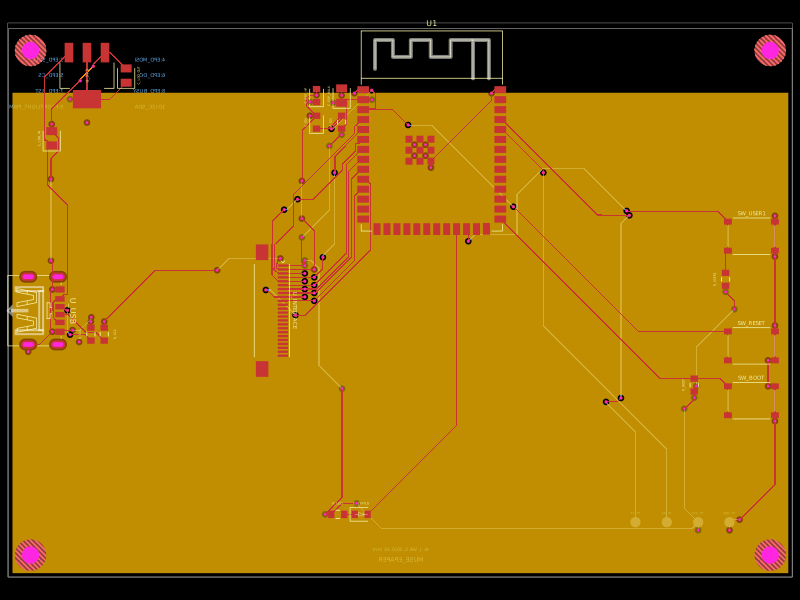 More from this authorShiboSoftwareDev/muse-reterminal-e1001-replacementA four-layer ESP32-S3 e-paper carrier board with USB-C power, AMS1117 3.3V regulation, 24-pin FFC interface, reset/boot and user buttons, status LED, decoupling passives, test points, mounting holes, and ground/power planes.
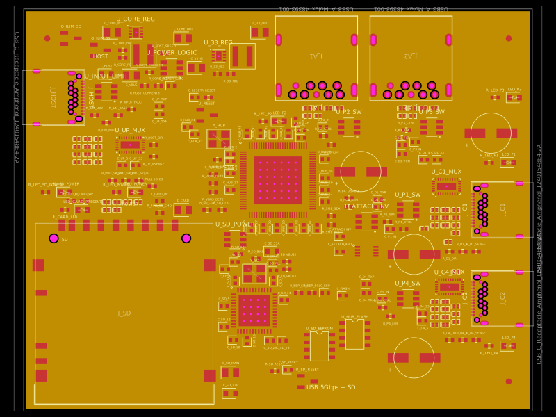 Similar packagegokul/usb3-sd-hubEngineering draft: four-layer, computer-powered USB 3 hub with one USB-C host socket, two USB-C and two USB-A accessory sockets, and a full-size SD slot. Board and three schematic previews are available. Routing and production checks are incomplete; not fabrication ready.
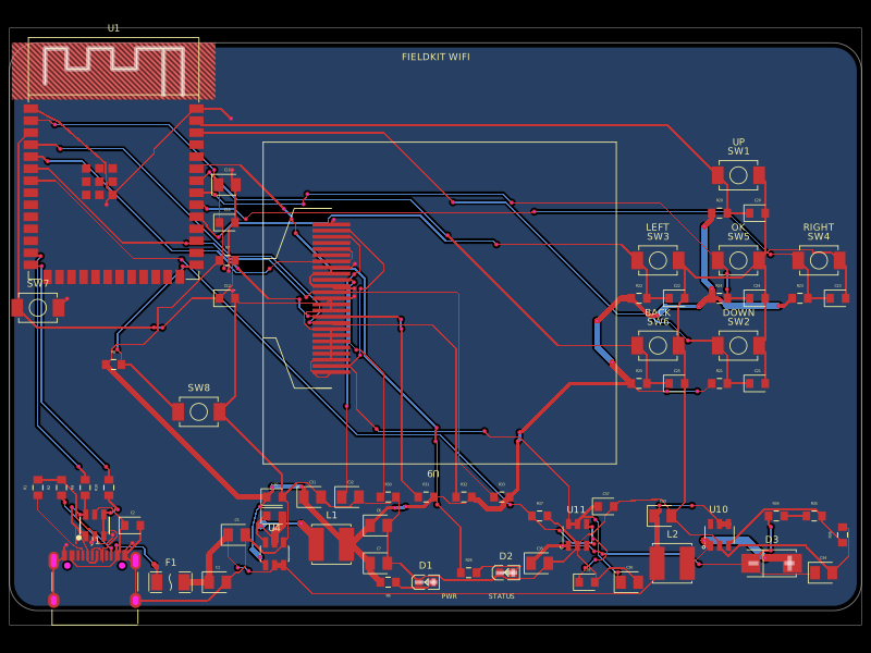 Discover something newgokul/fieldkit-usbUSB-C-powered ESP32-S3 Wi-Fi/Bluetooth handheld with an SMD 128x32 OLED, six navigation buttons, USB-C power/data, complete checked routing, and four native schematic sheets.