MustafaMulla29/rp2040-bldc-motor-controller-new
73×72 mm 4-layer USB‑C PD (5/9/15/20 V) RP2040 controller PCB with protected power switching, MCT8329A sensorless BLDC three-phase MOSFET bridge, USB data/programming, onboard controls, and three motor outputs feeding a 2212 motor through rigid bullet adapters.
- Version
- 0.3.100
- License
- unset
- Stars
- 0
manufacturing/stencil-process-screen.json
{
  "status": "PROCESS_REVIEW_FINDINGS_FACTORY_APPROVAL_NOT_OBTAINED",
  "checkedAt": "2026-10-23T12:06:58.034505+00:00",
  "pcbSha256": "1ca490a5a0406c9eb23e07d8cc6e17e092046133d1b0acf5909c8dcf034e8fbb",
  "stencilThicknessMm": 0.125,
  "topAperturesScreened": 536,
  "screeningGuideline": {
    "minimumAreaRatio": 0.66,
    "minimumAspectRatio": 1.5,
    "source": "https://www.analog.com/en/resources/app-notes/AN-772.html",
    "scope": "General process screen, not a universal DRC limit or proof that a specific factory process fails."
  },
  "processFindings": [
    {
      "component": "U1",
      "apertures": 24,
      "dimensionsMm": [
        [
          0.19600672,
          0.48999902
        ]
      ],
      "minimumAreaRatio": 0.5834953577094639,
      "minimumAspectRatio": 1.56805376,
      "nativeGerberVerified": true
    },
    {
      "component": "U5",
      "apertures": 56,
      "dimensionsMm": [
        [
          0.13999972,
          0.5950076999999999
        ]
      ],
      "minimumAreaRatio": 0.45333371680979223,
      "minimumAspectRatio": 1.11999776,
      "nativeGerberVerified": true
    },
    {
      "component": "U7",
      "apertures": 36,
      "dimensionsMm": [
        [
          0.13999972,
          0.48999902
        ]
      ],
      "minimumAreaRatio": 0.43555468444444445,
      "minimumAspectRatio": 1.11999776,
      "nativeGerberVerified": true
    }
  ],
  "allFindingFlashesMatchedNativeGerber": true,
  "q7BoardOrientation": {
    "status": "PASS_MANUFACTURER_PINOUT_AND_AUTHORED_CPL",
    "rotationDegrees": 90,
    "positionMm": [
      -14.7,
      19.6
    ],
    "sourcePins": [
      1,
      2,
      3
    ],
    "gatePin": 4,
    "drainPin": 5,
    "source": "https://www.diodes.com/datasheet/download/DMT6009LFG.pdf",
    "exactFactoryLibraryStatus": "Exact C439728 library imported and public footprint preview verified. Numbered-pad datum matches PCB/CPL. Order-specific factory placement approval is still pending."
  },
  "replacementPartsMinimumAreaRatios": {
    "Q1": 0.6995804195804196,
    "Q2": 0.6995804195804196,
    "Q7": 0.7349874173991927,
    "U12": 0.9955490502296119,
    "D4": 2.9644597568249207,
    "C71": 2.2112582781456953
  },
  "disposition": [
    "Do not describe the existing exported stencil as process-qualified. Exposed-pad geometry checks pass, but perimeter apertures need review.",
    "U7 peripheral apertures are 0.14 x 0.49 mm; TI REE0036A gives a 0.20 x 0.60 mm example at 0.125 mm stencil thickness. The export differs from that manufacturer example.",
    "U5 peripheral apertures are 0.14 x 0.595 mm. Confirm final apertures/thickness with the assembler; changing only to a 0.1 mm stencil does not bring these existing openings above the 0.66 screening guideline.",
    "U1 has 24 pill-shaped peripheral openings, 0.196 x 0.49 mm, also below the area-ratio guideline at 0.125 mm thickness.",
    "Potential remedies are revising native perimeter paste apertures and/or a qualified stencil process. No stencil or PCB geometry changed during this recheck.",
    "JLCPCB generates production stencil data after SMT verification; local tests cannot issue its approval or verify its unreleased machine-placement data."
  ],
  "evidenceSources": [
    "https://www.ti.com/lit/ds/symlink/mct8329a.pdf#page=163",
    "https://jlcpcb.com/help/article/smt-stencil-data-prepared-for-smt-orders",
    "https://jlcpcb.com/user-center/lcsvg/svg.html?code=C439728&detail=1"
  ]
}
Related Packages
 More from this authorMustafaMulla29/MC-MP-symbolsThis code defines a 10mm x 10mm schematic diagram featuring two integrated circuit components ("MC" and "MP") with their respective physical symbols, including outer rings, lobed shapes, connection lines, and ports.
 Similar packageAnasSarkiz/rp2040-bldc-servo-controllerRP2040-based motor-control board integrating a DRV8316 three-phase gate driver, AS5047P magnetic position sensor, USB-C power/communications, STUSB4500 USB-PD controller, SPI flash, and THVD1450 RS-485 transceiver.
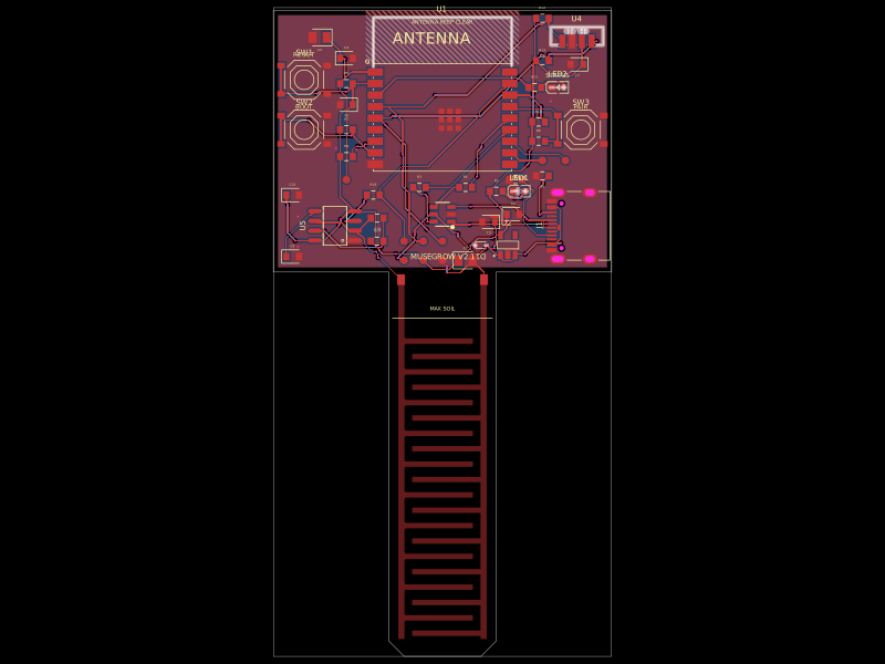 Discover something newgokul/musegrowUSB‑C powered ESP32‑C3 controller board with regulated 3.3 V supply, USB ESD protection, buttons/status LEDs, ambient-light I²C sensing, and a 555-driven capacitive soil-moisture electrode.