MustafaMulla29/rp2040-bldc-motor-controller-new
A tscircuit package created by MustafaMulla29.
- Version
- 0.3.101
- License
- unset
- Stars
- 0
manufacturing/factory-review-request.md
# Factory engineering review request — 23 October 2026

Status: tested replacements applied to main with user approval on 23 October 2026.
No factory submission, response, order or payment yet.

Please quote **five PCBs: two fully assembled and three bare** for
rp2040-bldc-motor-controller-new. These are unprogrammed engineering prototypes.
Use the matching Gerbers, BOM and reviewed CPL in this package. Do not fabricate
until sourcing and the engineering questions below have been resolved.

## Fabrication and assembly

- Board: 73 × 72 mm, four layers, 1.6 mm, JLC04161H-3313; 1 oz outer and
  0.5 oz inner copper. Preserve the supplied board outline and component lands.
- Assemble all 157 top-side positions on each of the two assembled units.
  The 16 service pads are bare copper, not purchased components. No bottom
  component placement is requested.
- Include soldering of C93, J10–J12 and RV1 and the J1/J19 USB shell tabs.
  Confirm fixture/rail requirements and clearance for C93's 20 mm body.
- Quote the three remaining boards as bare PCBs, without component kits.
- Do not program RP2040 flash, STUSB4500 NVM or MCT8329A EEPROM. Do not attach
  a motor or apply a PD source for an automated functional test. This package
  contains no commissioned motor firmware image; quote normal assembly
  inspection and electrical bare-board testing separately from functional testing.

## Sourcing questions

The public catalog was checked on 23 October 2026. Please confirm current stock,
assembly loss allowances and any procurement lead times for all 61 BOM lines.
The CSV includes demand for the two populated boards; it is not a reservation.

| Designators | Exact part / catalog number | Population demand | Public stock |
| --- | --- | ---: | ---: |
| Q1, Q2 | SI7111EDN-T1-GE3 / C5690133 | 4 | 9 |
| C71 | C3225X7R1H106KT000E / C432929 | 2 | 19,975 |
| Q7 | DMT6009LFG-7 / C439728 | 2 | 22 |
| U12 | LM74700QDBVTQ1 / C2653623 | 2 | 73 |
| D4 | Bourns SMBJ22A / C3720133 | 2 | 64 |

All 61 current BOM lines have public stock covering population only. Please
confirm factory minimums and loss allowances, especially Q1/Q2 with nine listed.
Do not silently omit positions or
substitute another part/manufacturer. Confirm all 157 designators are selected
for assembly after matching the BOM; an unchecked position is not authorized DNP.

## Engineering decisions to return

1. **Placement:** provide the numbered-pad placement preview using
   `cpl-reviewed.csv`. Review J1/J19's shell-slot datum, RV1's corrected Alps
   mounting pattern, SW4's corrected contact pitch, Q7's asymmetric datum,
   LED1's common-cathode pinout, all IC/diode orientations and C93 polarity.
   Q1/Q2 now use PowerPAK 1212-8, not the previous SO-8. Q7 C439728's
   exact supplier import and public footprint preview are verified. Its numbered
   pads match the authored copper and reviewed CPL. Confirm the order placement.
   Do not replace the reviewed CPL with the native export's fallback positions.
2. **USB:** confirm the requested stack and calculate the actual L1/L2 routing
   for 90 Ω differential ±15%. Main width/gap is 0.15/0.15 mm; two short
   connector bridges are 0.125 mm wide and fanout gaps vary. Return any proposed
   copper changes for review before fabrication; a coupon alone is insufficient
   to assess the complete routed geometry.
3. **Stencil:** review the 0.125 mm starting thickness, U7's six-window drawing,
   U11's single opening, Q7's eight apertures and Q1/Q2's eight drain apertures
   each. Approve remaining exposed pads
   and small apertures. Native U7/Q7 windows are rectangular; U7 R0.05 rounding
   is a process request. Omit paste on test pads, ordinary THT holes and USB
   shell slots. No bottom SMT assembly is requested. Return the production
   stencil drawing or your proposed changes before its release.
   The full aperture screen now identifies U1's 24 peripheral openings (area
   ratio 0.583), U5's 56 (0.453), and U7's 36 (0.436) below the general 0.66
   guideline at 0.125 mm. U7's native 0.14 × 0.49 mm pin openings also differ
   from TI's 0.20 × 0.60 mm stencil example. See `stencil-process-screen.json`.
   Confirm revised apertures/thickness and the production process; do not
   treat passing exposed-pad geometry checks as approval of these small openings.
4. **Mixed assembly:** confirm the quote covers all through-hole joints and USB
   tabs, plus necessary fixtures and external panel rails/fiducials. Preserve
   connector access and the evaluation notice on every board, including bare units.

The attached checks establish exported geometry and numbered-pad alignment, not
your factory-library alignment or process approval. Please return the review
against the circuit hash in `release-validation.json` and identify any revisions.

References checked for this preparation:

- [JLCPCB BOM matching](https://jlcpcb.com/help/article/component-matching-guidelines-for-pcba-orders)
- [JLCPCB stencil preparation](https://jlcpcb.com/help/article/smt-stencil-data-prepared-for-smt-orders)
- [JLCPCB stackups](https://jlcpcb.com/impedance)
- [JLCPCB assembly capabilities](https://jlcpcb.com/capabilities/pcb-assembly-capabilities)
- [JLCPCB pre-order service](https://jlcpcb.com/help/article/what-is-jlcpcb-parts-pre-order-service)
Related Packages
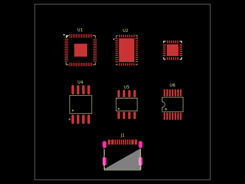
 More from this authorMustafaMulla29/MC-MP-symbolsThis code defines a 10mm x 10mm schematic diagram featuring two integrated circuit components ("MC" and "MP") with their respective physical symbols, including outer rings, lobed shapes, connection lines, and ports.
 Similar packageAnasSarkiz/rp2040-bldc-servo-controllerRP2040-based motor-control board integrating a DRV8316 three-phase gate driver, AS5047P magnetic position sensor, USB-C power/communications, STUSB4500 USB-PD controller, SPI flash, and THVD1450 RS-485 transceiver.
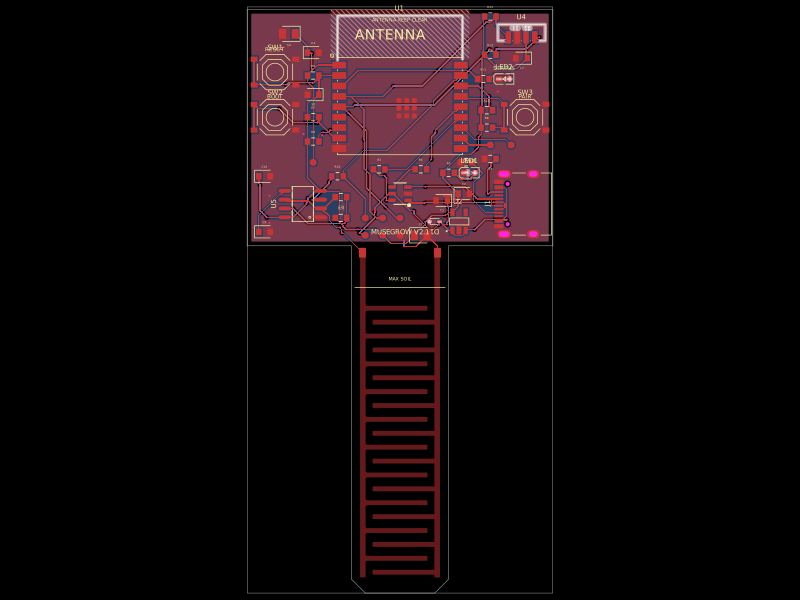 Discover something newgokul/musegrowUSB‑C powered ESP32‑C3 controller board with regulated 3.3 V supply, USB ESD protection, buttons/status LEDs, ambient-light I²C sensing, and a 555-driven capacitive soil-moisture electrode.