MustafaMulla29/rp2040-bldc-motor-controller-new
73×72 mm 4-layer USB‑C PD (5/9/15/20 V) RP2040 controller PCB with protected power switching, MCT8329A sensorless BLDC three-phase MOSFET bridge, USB data/programming, onboard controls, and three motor outputs feeding a 2212 motor through rigid bullet adapters.
- Version
- 0.3.100
- License
- unset
- Stars
- 0
docs/bringup-acceptance.md
# Prototype acceptance record — NOT RUN

Record board serial, BOM revision, circuit SHA, firmware revision, charger PDOs,
cable, motor and instruments for each run. CAD and mock-bus test results do not
fill in this record. This is an unprogrammed engineering prototype, not a
production-ready controller.

| Gate | Procedure and evidence | Acceptance |
| --- | --- | --- |
| Factory review | Confirm stack, actual USB impedance geometry, numbered-pad placement preview, exact BOM, stencil drawing and five THT parts plus USB tabs. | Written review of the matching export; substitutions re-reviewed. |
| Unpowered board | Inspect polarity, solder bridges, socket/adapter fit, mounting clearance and SW4 contacts; measure rail resistance. | Matches schematic and assembly drawing; investigate unexpected shorts before power. |
| Logic bring-up | SW4 OFF, motor disconnected. Use the documented 5 V-only provisioning setup. Measure 3.3 V and record input current, then program RP2040 and provision STUSB4500. | Stable logic supply, no abnormal heating; verify correct NVM including power-only flag after removing all power. |
| PD profiles | With motor absent and SW4 OFF, exercise 5/9/15/20 V, unsupported-profile rejection, cable removal and 20-to-5 V transitions. Measure VBUS and VMOTOR independently. | Correct explicit contract, source capability and measured voltage; no unintended ARM pulse. Cold restart selects 9 V. |
| USB data | Test both J1 plug orientations, DATA-only, PD-only and both plugged. Stream data while switching PD voltage with motor disabled. | Enumeration/traffic pass without resets or backpower; log input-current and rail behavior. |
| OFF/protection | Verify SW4 OFF removes motor power and clamps ARM, PD loss/fault disarms, and restart requires a fresh ARM action. | No automatic restart. Validate actual hardware signals, not only printed status. |
| Current budget | Measure separate logic-branch and motor-feed currents, startup/inrush and U11 trip behavior; calibrate ADC28. | Measured logic loads fit current-budget.json allocations and total input stays inside the negotiated source capability. Verify the switch's transient response separately. |
| Motor commissioning | Commission the MCT8329A profile and ADC calibration, then review/exercise the new knob runtime per `knob-firmware.md`. With rotor guarded and no propeller, begin unloaded at 9 V. Scope gates, shunt and bus; verify direction, current-limit and fault behavior. | Set and record an actual phase-current limit. No shoot-through, unsafe gate waveforms, uncontrolled restart or bus overvoltage. Test rapid SW4 toggling: software has no dedicated position feedback. Do not infer phase current from R13. |
| Loaded/thermal tests | Increase to a defined load, measure phase/input currents, MOSFET/switch/shunt/connector temperatures and bus transients during startup and stopping. Repeat intended voltage/cable combinations. | Documented allowable currents, temperatures and stopping energy, within all component operating limits. D4 is not a continuous regeneration dump. |
| 5 V qualification | Test selected 5 V with intended cables and load; calibrate voltage sense, record ripple and shutdown response. | Driver supply stays within its operating range; shutdown occurs before undervoltage. Do not claim universal 5 V motor operation from one favorable setup. |

Motor configuration, calibration and runtime hardware qualification are incomplete.
The knob application is implemented but ships with its commissioning profile
unset; the supplied applications therefore hold SPEED and ARM low, and
motor-related acceptance rows remain untested. Production also needs a repeatable
programming/test fixture, specified supported motors/loads and an approved test
report.
Related Packages
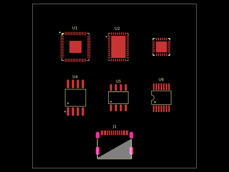
 More from this authorMustafaMulla29/MC-MP-symbolsThis code defines a 10mm x 10mm schematic diagram featuring two integrated circuit components ("MC" and "MP") with their respective physical symbols, including outer rings, lobed shapes, connection lines, and ports.
 Similar packageAnasSarkiz/rp2040-bldc-servo-controllerRP2040-based motor-control board integrating a DRV8316 three-phase gate driver, AS5047P magnetic position sensor, USB-C power/communications, STUSB4500 USB-PD controller, SPI flash, and THVD1450 RS-485 transceiver.
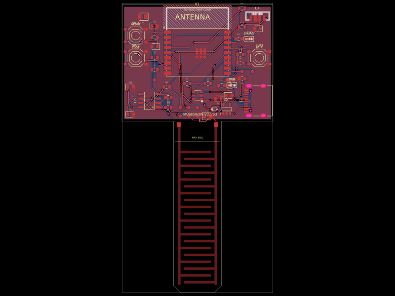 Discover something newgokul/musegrowUSB‑C powered ESP32‑C3 controller board with regulated 3.3 V supply, USB ESD protection, buttons/status LEDs, ambient-light I²C sensing, and a 555-driven capacitive soil-moisture electrode.