MustafaMulla29/rp2040-bldc-motor-controller-new
73×72 mm 4-layer USB‑C PD (5/9/15/20 V) RP2040 controller PCB with protected power switching, MCT8329A sensorless BLDC three-phase MOSFET bridge, USB data/programming, onboard controls, and three motor outputs feeding a 2212 motor through rigid bullet adapters.
- Version
- 0.3.100
- License
- unset
- Stars
- 0
assembly/dimensions.ts
// Millimetres. Published dimensions and display-only assumptions are separate.
export const dimensions = {
  motor: {
    // Text specifies nominal 28 mm; the drawing calls out 27.8 mm.
    // Use the larger published nominal diameter for the body envelope.
    bodyDiameter: 28, drawingBodyDiameter: 27.8, bodyHeight: 24,
    overallWithoutCap: 38, shaftAboveBody: 14, // Derived: 38 - 24.
    shaftEnvelopeDiameter: 7.98, shaftThread: "M6", shaftAcrossFlats: 6.8,
    mountingHoleThread: "M3", mountingHoleCount: 4,
    opposedMountingHolePitches: [16, 19],
    plugDiameter: 3.5,
    source: "https://www.amazon.com/dp/B075DD16LK",
    drawing: "https://m.media-amazon.com/images/I/61prmpd-BOL._AC_SL1100_.jpg",
    status: "Published motor envelope dimensions; detailed surfaces, cap and lead geometry unresolved",
  },
  // These values are retained only for the explicitly illustrative connected
  // connection view. They are not measurements or specifications of this motor.
  illustrativeLeads: {
    wireDiameter: 2.4, heatShrinkDiameter: 4.5, heatShrinkLength: 9,
    status: "Display-only motor wire and heat-shrink dimensions; unverified",
  },
  socket: {
    part: "AMASS 24.243.4", jlcpcb: "C7437324", nominalBore: 4,
    overallLength: 24, bodyHeight: 13, pinPitch: 15.7,
    source: "https://jlcpcb.com/partdetail/Changzhou_AmassElec-24_2434/C7437324",
    status: "PCB footprint, courtyard and OBJ imported from the exact supplier part",
  },
  motorLead: {
    model: "adaptercable_a(wire_end_d2.4mm)_b(bullet1_d3.5mm_gmale)",
    genericMaleContactDepth: 7, genericMaleBodyDepth: 12.25,
    status: "Native motor cable with a fixed wire exit and a male bullet; generic contact dimensions",
  },
  adapter: {
    part: "BDHI B117-5", femaleNominalDiameter: 3.5, maleNominalDiameter: 4,
    source: "https://www.amazon.com/dp/B07Z4FRQNX",
    // Only the mating diameters/genders are supported by the selected listing.
    // No dimensioned body drawing has been obtained. Retain explicitly marked
    // study dimensions instead of presenting them as verified measurements.
    illustrativeMaleLength: 12, illustrativeSleeveLength: 14,
    illustrativeSleeveDiameter: 6, illustrativeFemaleOuterDiameter: 5.2,
    genericFemaleContactDepth: 7, illustrativeBoardInsertion: 8,
    status: "Rigid shape; nominal end sizes verified, body and insertion dimensions unverified",
  },
  layout: {
    motor: [12, 127, 0] as [number, number, number],
    // Socket placement is read from compiled PCB CAD; no duplicated world positions.
  },
} as const

export const geometryNotes = [
  "Configurable-PD trial — 5/9/15/20 V, default 9 V: 73 x 72 mm, all 155 fitted components on top, 16 fabricated test pads, exact imported J10/J11/J12 socket geometry.",
  "Three of the assembly.cable primitives are the motor's original leads. Each starts at a fixed wire exit on the motor and ends with a native 3.5 mm male bullet inside a rigid adapter.",
  "Each rigid adapter is a custom native CAD model using upstream jscad male and female bullet meshes and a red insulating sleeve. There is no wire inside or between the adapter ends.",
  "Adapter chain: motor male 3.5 mm -> adapter female 3.5 mm; adapter male 4 mm -> PCB female 4 mm. All six interfaces are seated in the model.",
  "The exact BDHI listing supplies nominal diameters/genders, not a dimensioned body drawing. Its 12 mm pin, 14 mm sleeve, 6 mm sleeve OD and 5.2 mm female contact OD are illustrative, not supplier dimensions.",
  "Modeled insertion is 7 mm at the motor side and 8 mm into the PCB. These depths are illustrative and do not prove physical fit or retention.",
  "Motor envelope dimensions are published; motor wire diameter/length/exit position and heat-shrink dimensions remain unverified.",
  "A documented local wire_end extension represents permanent motor attachment without inventing a plug at the motor. Named component-local ports resolve to the core mating-point boundary; the native cable path/mesh pipeline is retained.",
  "No fabricated PCB connector, hidden cable-end mesh, modified DRC record or PCB geometry is used.",
]
Related Packages
 More from this authorMustafaMulla29/MC-MP-symbolsThis code defines a 10mm x 10mm schematic diagram featuring two integrated circuit components ("MC" and "MP") with their respective physical symbols, including outer rings, lobed shapes, connection lines, and ports.
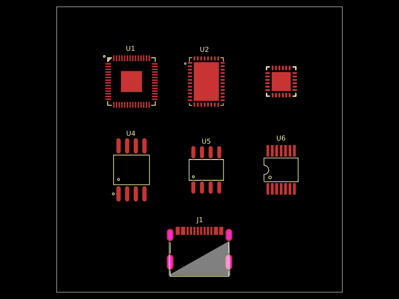 Similar packageAnasSarkiz/rp2040-bldc-servo-controllerRP2040-based motor-control board integrating a DRV8316 three-phase gate driver, AS5047P magnetic position sensor, USB-C power/communications, STUSB4500 USB-PD controller, SPI flash, and THVD1450 RS-485 transceiver.
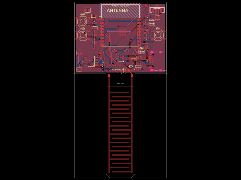 Discover something newgokul/musegrowUSB‑C powered ESP32‑C3 controller board with regulated 3.3 V supply, USB ESD protection, buttons/status LEDs, ambient-light I²C sensing, and a 555-driven capacitive soil-moisture electrode.