AnasSarkiz/muse-voice-remote
Muse Voice Remote — bare ESP32-S3R8, 155 TOP JLCPCB parts with real supplier CAD, native 3D assembly and GLB exports. Revised 17 mm case allocation; 0.30 mm via drill /0.45 mm pad. Checked prototype PCB; mechanical, RF and MUSE qualification pending.
- Version
- 1.3.2
- License
- unset
- Stars
- 0
vendor/espressif-bare-s3/esp32-s-series-digital-power-supply.inc
{IDF_TARGET_DIG_POWER_PIN:default="pin17 VDD3P3_CPU", esp32="pin37 VDD3P3_CPU", esp32s2="pin27 VDD3P3_RTC_IO and pin45 VDD3P3_CPU", esp32s3="pin46 VDD3P3_CPU", esp32c6="pin5 VDDPST1 and pin28 VDDPST2", esp32h2="pin9 VDDPST1 and pin20 VDDPST2", esp32c5="VDDPST1 (pin8), VDDPST2 (pin24), and VDDPST3 (pin39)"}

{IDF_TARGET_DIG_POWER_RTC_PIN:default="to be defined", esp32s3="pin 20 VDD3P3_RTC", esp32="pin 20 VDD3P3_RTC"}

{IDF_TARGET_DIG_POWER_PIN_VOL:default="3.0 V ~ 3.6 V", esp32="1.8 V ~ 3.6 V", esp32s2="3.0 V ~ 3.6 V and 2.8 V ~ 3.6 V"}

{IDF_TARGET_VDD_POWER:default="VDD_SPI", esp32="VDD_SDIO"}

{IDF_TARGET_RSPI_VALUE:default="to be defined", esp32="6", esp32s2="5", esp32s3="14"}

{IDF_TARGET_VDD_STRAPPING_PIN:default="to be defined", esp32="MTDI", esp32s3="GPIO45"}

{IDF_TARGET_EFUSE_POWER_CTRL:default="to be defined", esp32="EFUSE_SDIO_FORCE", esp32s3="EFUSE_VDD_SPI_FORCE"}

{IDF_TARGET_EFUSE_TIEH:default="to be defined", esp32="EFUSE_SDIO_TIEH", esp32s3="EFUSE_VDD_SPI_TIEH"}

.. only:: esp32s3

   {IDF_TARGET_NAME} has {IDF_TARGET_DIG_POWER_PIN} as the digital power supply pin, and {IDF_TARGET_DIG_POWER_RTC_PIN} as the RTC and partial digital power supply pin, with an operating voltage range of {IDF_TARGET_DIG_POWER_PIN_VOL}. It is recommended to add a 0.1 μF capacitor close to the digital power supply pins in the circuit.

.. only:: esp32

   {IDF_TARGET_NAME} has {IDF_TARGET_DIG_POWER_PIN} as the digital power supply pin, with an operating voltage range of {IDF_TARGET_DIG_POWER_PIN_VOL}. {IDF_TARGET_NAME} also has {IDF_TARGET_DIG_POWER_RTC_PIN} as the RTC and partial digital power supply pin, with an operating voltage range of 2.3 V ~ 3.6 V. It is recommended to add a 0.1 μF capacitor close to the digital power supply pins in the circuit.

.. only:: esp32s2 or esp32s3

   Pin {IDF_TARGET_VDD_POWER} serves as the power supply for the external device at either 1.8 V or 3.3 V (default). It is recommended to add extra 0.1 μF and 1 μF decoupling capacitors close to {IDF_TARGET_VDD_POWER}. Please do not add excessively large capacitors.

   - When {IDF_TARGET_VDD_POWER} operates at 1.8 V, it is powered by {IDF_TARGET_NAME}'s internal LDO. The typical current this LDO can offer is 40 mA.
   - When {IDF_TARGET_VDD_POWER} operates at 3.3 V, it is driven directly by VDD3P3_RTC through a {IDF_TARGET_RSPI_VALUE} Ω resistor, therefore, there will be some voltage drop from VDD3P3_RTC.

.. only:: esp32

  Pin {IDF_TARGET_VDD_POWER} serves as the power supply for the external device at either 1.8 V or 3.3 V (default).

  - When {IDF_TARGET_VDD_POWER} is in 1.8 V mode, it is powered by {IDF_TARGET_NAME}'s internal LDO, which can provide a maximum current of 40 mA and an output voltage range of 1.65 V ~ 2.0 V. It is recommended to add a 2 kΩ pull-down resistor and a 4.7 μF capacitor to ground at the {IDF_TARGET_VDD_POWER} pin.

  - When {IDF_TARGET_VDD_POWER} is in 3.3 V mode, it is powered by VDD3P3_RTC through an internal resistor of about {IDF_TARGET_RSPI_VALUE} Ω. Therefore, there will be some voltage drop between {IDF_TARGET_VDD_POWER} and VDD3P3_RTC. It is recommended to add a 1 μF filter capacitor close to the {IDF_TARGET_VDD_POWER} pin.

.. attention::

   - When using VDD{IDF_TARGET_VDD_POWER}_SPI as the power supply pin for in-package or off-package 3.3 V flash/PSRAM, please ensure that VDD3P3_RTC remains above 3.0 V to meet the operating voltage requirements of the flash/PSRAM, considering the voltage drop mentioned earlier.

   - Note that VDD3P3_RTC cannot supply power alone; all power supplies must be powered on at the same time.

.. only:: esp32s3 or esp32

   Depending on the value of {IDF_TARGET_EFUSE_POWER_CTRL}, the {IDF_TARGET_VDD_POWER} voltage can be controlled in two ways, as Table :ref:`tab-vdd-spi-voltage-control` shows.

   .. list-table:: {IDF_TARGET_VDD_POWER} Voltage Control
    :name: tab-vdd-spi-voltage-control
    :header-rows: 1
    :widths: 10 10 10 20 50
    :align: center

    * - {IDF_TARGET_EFUSE_POWER_CTRL}
      - {IDF_TARGET_VDD_STRAPPING_PIN}
      - {IDF_TARGET_EFUSE_TIEH}
      - Voltage
      - {IDF_TARGET_VDD_POWER} Power Source
    * - 0
      - 0
      - Ignored
      - 3.3 V
      - VDD3P3_RTC via R\ :sub:`SPI` (default)
    * - 0
      - 1
      - Ignored
      - 1.8 V
      - Flash Voltage Regulator
    * - 1
      - Ignored
      - 0
      - 1.8 V
      - Flash Voltage Regulator
    * - 1
      - Ignored
      - 1
      - 3.3 V
      - VDD3P3_RTC via R\ :sub:`SPI`

{IDF_TARGET_VDD_POWER} can also be driven by an external power supply.

It is recommended to use the {IDF_TARGET_VDD_POWER} output to supply power to external or internal flash/PSRAM.
Related Packages
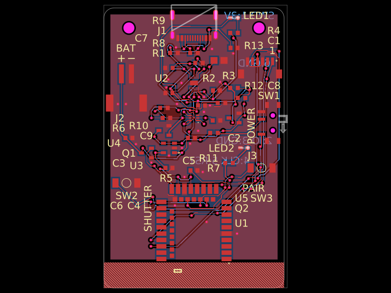 More from this authorAnasSarkiz/magnetic-shutter-remote--01a0f81fA compact USB‑C rechargeable battery device with BQ25185 charging, 3.3‑V regulation and protection, E73 Bluetooth control, temperature monitoring, status/charge LEDs, shutter/pair/power switches, and a mechanically enclosed Li‑Po battery with docking/antenna provisions.
 Similar packagemohan-bee/esp32-c3This hardware design integrates an ESP32-C3 microcontroller, a USB-C connector, a power management IC (AP2112-3.3V regulator), a USB-to-Serial converter (CH340C), several resistors, capacitors, and user-accessible headers to facilitate USB communication, power regulation, and general I/O interfacing.
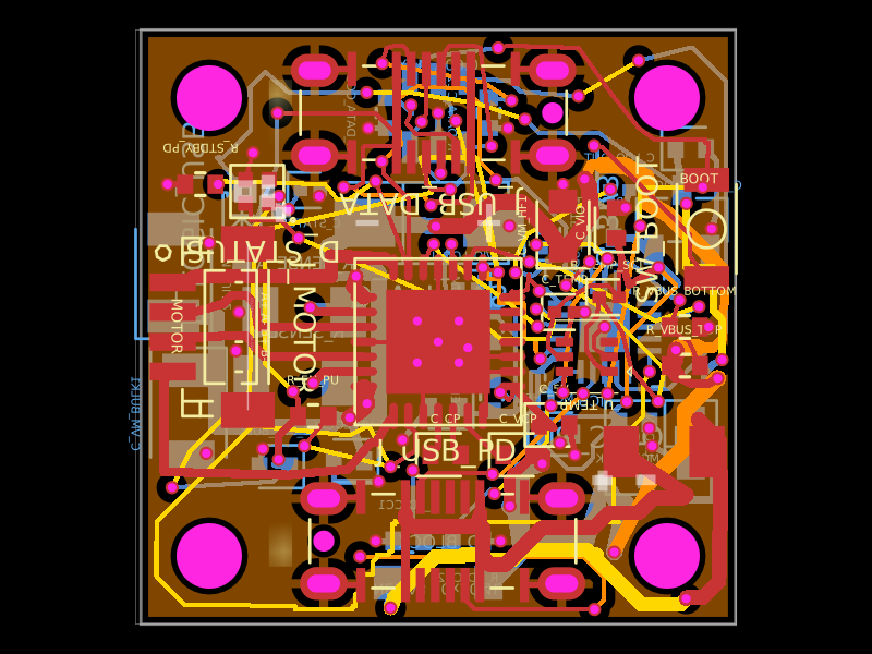 Discover something newShiboSoftwareDev/nema8-20mm-dual-usbc-stepper-controllerA compact 20 mm four-layer USB‑C stepper-controller PCB combining CH32X035 MCU control, TMC2209 motor driving, USB‑C PD/data interfaces, protection/power regulation, temperature/LED status hardware, and NEMA8 motor connectivity.