AnasSarkiz/NEMA14_CH32X035G8U6
A NEMA stepper motor is shown with proposed M3 screws/spacers, four wired motor leads and splices, and a JST SHR-04V-S connector.
- Version
- 1.12.2
- License
- ISC
- Stars
- 0
src/layer-routing-policy.json
{
  "inner1_allowed_nets": [
    "A_MINUS",
    "A_PLUS",
    "BOOT_PAD",
    "BUZZER_GATE",
    "BUZZER_PWM",
    "B_MINUS",
    "B_PLUS",
    "DATA_CC1",
    "DATA_CC2",
    "DATA_PRESENT",
    "DATA_VBUS",
    "DCK",
    "DIO",
    "DIR",
    "ENABLE_N",
    "GND",
    "LED_B",
    "LED_G",
    "LED_R",
    "PD_CC1",
    "PD_CC2",
    "PD_GOOD",
    "PD_VBUS",
    "PWR_LED_A",
    "QSPI_SCLK",
    "QSPI_SD0",
    "QSPI_SD1",
    "QSPI_SD2",
    "QSPI_SD3",
    "QSPI_SS",
    "RUN",
    "SLEEP",
    "STATUS_B_C",
    "STATUS_B_K",
    "STATUS_G_C",
    "STATUS_G_K",
    "STATUS_R_C",
    "STATUS_R_K",
    "STEP",
    "SWCLK",
    "SWDIO",
    "TEMP_SCL",
    "TEMP_SDA",
    "V1V1",
    "V3V3",
    "VM_SENSE",
    "XIN",
    "XOUT",
    "XTAL_OUT"
  ],
  "maximum_inner1_trace_section_length_mm": 30,
  "maximum_clock_or_flash_inner1_section_mm": 15,
  "maximum_A_MINUS_inner1_section_mm": 8,
  "minimum_A_MINUS_inner1_width_mm": 0.3,
  "USB_inner_signal_tracks_allowed": false,
  "required_main_inner1_ground_region_area_mm2": 700,
  "rationale": "Motor phase inner1 transitions are limited to 12 mm at >=0.30 mm width for the 0.40 A worst-case phase budget. They must independently pass IPC thermal screening on >=17.5 um internal copper, >=700 mm2 continuous grounded inner1 fill, full-width USB ground reference, connectivity and all native/CAM clearances. At 12 mm a 0.30 x 0.0175 mm conductor has approximately 39.4 milliohm resistance, 15.8 mV drop and 6.3 mW loss at 0.40 A. These calculations do not establish bench thermal performance.",
  "maximum_total_phase_inner1_length_mm": 12,
  "minimum_phase_inner1_width_mm": 0.3,
  "USB_construction_reference_buffer_mm": 0.4,
  "USB_reference_requires_full_track_width": true,
  "USB_construction_reference_rationale": "Pair outer edge is 0.330 mm from the centreline. A 0.400 mm construction buffer plus the existing 0.15 mm copper clearance and 0.02 mm grid margin leaves 0.04 mm beyond the 0.20 mm ground-fill setback. Final exact full-track ground-reference geometry remains mandatory."
}
Related Packages
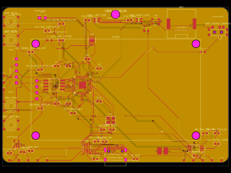 More from this authorAnasSarkiz/vibe_GoblinThese code snippets define various physical electronic components such as ICs, connectors, sensors, LEDs, and chips, specifying their pin layouts, footprint pads, silkscreen markings, courtyard outlines, and 3D CAD models for placement on PCB boards.
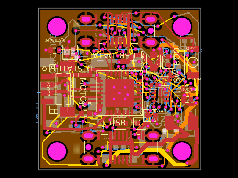 Similar packageShiboSoftwareDev/nema8-20mm-dual-usbc-stepper-controllerA compact 20 mm four-layer USB‑C stepper-controller PCB combining CH32X035 MCU control, TMC2209 motor driving, USB‑C PD/data interfaces, protection/power regulation, temperature/LED status hardware, and NEMA8 motor connectivity.
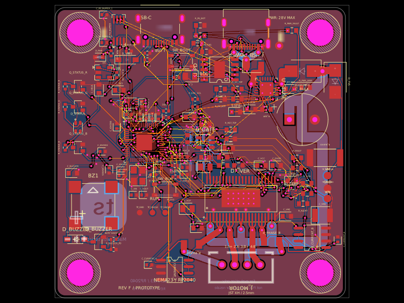 Discover something newimrishabh18/nema-23-stepper-controllerA four-layer NEMA23 stepper motor controller PCB featuring an RP2040 MCU, DRV8452 dual-phase driver, USB‑C PD power input/protection, current and temperature sensing, status LED/buzzer, and optional magnetic encoder.