AnasSarkiz/NEMA14_CH32X035G8U6
A NEMA stepper motor is shown with proposed M3 screws/spacers, four wired motor leads and splices, and a JST SHR-04V-S connector.
- Version
- 1.12.2
- License
- ISC
- Stars
- 0
docs/reference-feedback.md
> Historical baseline document: this predates the opposite-edge v1.11.0 draft. See [current draft and blockers](opposite-edge-review.md) for current evidence.

# Reference feedback and electrical review — v1.5.0

The original delivered board had no fitted power/debug LED, RGB status LED, temperature sensor or buzzer. This revision adds all four using the live [Rishabh reference](https://tscircuit.com/imrishabh18/rp2040-motor-controller) release `e8d285f7-c3d8-46f5-9a54-344fdde0124e`. Reference section sources and release metadata are retained under `references/reference-feedback/`. Existing connected physical pins and passive values are compared with the frozen Git baseline in `artifacts/reference-feedback/preserved-electrical-interfaces.json`.

## Fitted circuits

- Power/debug LED: XL-1608SURC-06 C965799, 330 ohm C25104 from 3.3 V. This indicates power; software status is provided by the RGB LED.
- RGB status LED: LTST-C19HE1WT C458749, common anode on fixed programming USB 5 V (DATA_VBUS), three 1 kohm resistors and DTC114EU3HZGT106 C509876 digital NPN sinks. RGB requires the programming USB supply; PD-only power does not light this LED, matching the reference connection.
- Temperature: TMP102AIDRLR C99269, ADD0 grounded (7-bit address 0x48), 100 nF bypass, 4.7 kohm SDA/SCL pull-ups to 3.3 V. ALERT is unconnected as in the reference. Firmware must poll temperature and implement alarm/shutdown behavior. This sensor measures its PCB location; motor winding temperature is not measured.
- Buzzer: HYG-8503A C7544813 externally driven magnetic transducer, 3.3 V positive terminal, AO3400A C20917 low-side switch, 100 ohm gate resistor, 100 kohm reset-off pull-down and 10 uF local bypass. PWM firmware is required. The reference's PMEG6020ELRX C478000 (60 V / 2 A) power diode is reused as the flyback diode in place of B5819W_SL C8598: cathode to 3.3 V, anode to the switched negative terminal. This preserves the reference drive topology with a native smaller land pattern; the components are not all byte-identical to the reference.

The previous HT7533-1 100 mA linear supply is replaced by the AP63203WU-7 fixed 3.3 V buck with the same supplier parts and component values as the RP2040 board. A 120 mA buzzer alone exceeds the old regulator rating. The buck permits programming-USB power through the blocking diode as well as negotiated 15 V PD. PCB temperature, transients and supply stability still require measurement.

## Firmware assignment

| Function | MCU assignment |
| --- | --- |
| RGB red | PA5 / pin 10 |
| RGB green | PA7 / pin 12 |
| RGB blue | PB0 / pin 13 |
| Buzzer PWM | TIM3_CH1 PA6 / pin 11 |
| Temperature SDA | Software I2C PB7 / pin 18 |
| Temperature SCL | Software I2C PB6 / pin 17 |

CH32 PB6/PB7 are GPIOs, not a CH32X035 hardware I2C alternate-function pair. Software I2C preserves the existing USB and WCH debug pins. RGB channel firmware must use GPIO/software PWM as appropriate. RP2040 assignments match the reference. Neither repository includes qualified firmware for these accessories, and the reference firmware is not a drop-in replacement for this A4988 controller.

## External connection standard

The programming USB-C duplicates D+ and D− receptacle contacts onto USB_DP and USB_DM, presents separate 5.1 kohm CC sink resistors, connects its VBUS contacts to fixed DATA_VBUS, grounds shell/GND contacts and leaves SBU unconnected. The PD USB-C sends CC1/CC2 to CH224K, supplies negotiated PD_VBUS and leaves USB data/SBU contacts unconnected. Never apply negotiated PD voltage to DATA_VBUS or the RGB anode.

The fitted B4B-PH-K-S(LF)(SN) C131334 JST PH top-entry motor header uses physical pins **1 A+, 2 A−, 3 B+, 4 B−**, matching the reference's external coil order. Positive coil paths in the reference additionally pass through current-sense circuitry; this board retains its A4988 outputs and current setting. Confirm the cable pin order from the manufacturer pin-1 view before connecting a motor.

## Evidence and limits

`circuit-verification.json` checks 92 physical connector/accessory/MCU pins, actual MPNs/values and byte-verified native footprints, courtyards, OBJ and STEP models. `every-trace-review.csv` inventories every delivered trace; its JSON adds every segment and via net. Native DRC, independent physical connectivity, width/current screening, real Gerber copper/drill comparison and native STEP mechanical checks are separate required evidence.

The CH32 board now uses four copper layers (35 um external, at least 17.5 um internal assumed for the screening), including a reserved inner1 ground plane, to route the additional circuits and their returns within the fixed outline. This changes fabrication cost. The outline remains exactly 35 × 35 mm. Four NPTH mounts remain exactly (±13, ±13), diameter 3.2 mm. Both GCT USB4145 sockets face upward (+Z) at nominal (±6.05, 15.15) mm. Two defined 10 mm housings have 2.1 mm nominal separation; actual footprint, drill and conservative 3D envelopes are checked. Maximum screw head diameter is 4 mm (DIN 920); the mechanical screen uses a 4.4 mm conservative envelope. Normal 5.4 mm M3 heads do not meet the layout constraint. The native top-entry JST and cable insertion space remain fitted and checked.

Static source agreement and a working reference do not establish that the assembled hardware works. USB signal integrity, regulator stability, buzzer supply transients/noise, RGB operation, temperature accuracy, phase current, PD negotiation, physical cables/threads and rear motor/adapter geometry require hardware verification. No rear-motor compatibility claim is made. Complete assembly CAM/stencil/silkscreen and pickup-angle qualification remains required before fabrication approval; see the actual current validation/CAM receipts.

The optional AS5600-ASOM C79815 and its two bypass capacitors are BOTTOM doNotPlace. They share the existing 3.3 V I²C bus (0x36 versus TMP102 0x48), are omitted from factory BOM/CPL and paste, and require later rear-shaft/magnet/firmware verification.
Related Packages
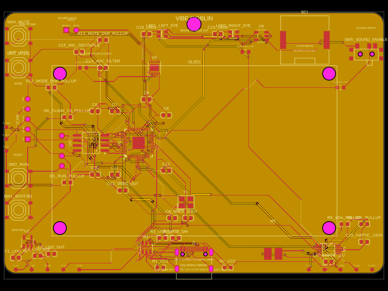 More from this authorAnasSarkiz/vibe_GoblinThese code snippets define various physical electronic components such as ICs, connectors, sensors, LEDs, and chips, specifying their pin layouts, footprint pads, silkscreen markings, courtyard outlines, and 3D CAD models for placement on PCB boards.
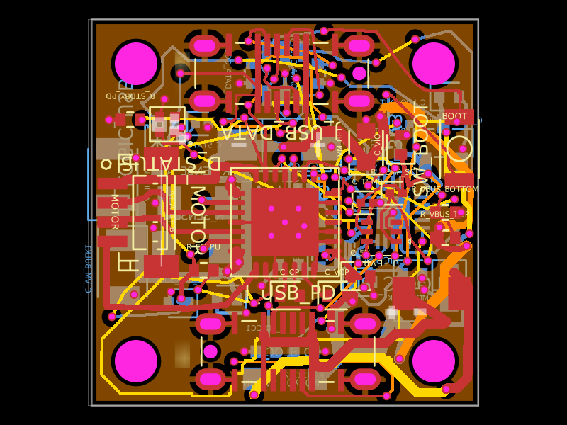 Similar packageShiboSoftwareDev/nema8-20mm-dual-usbc-stepper-controllerA compact 20 mm four-layer USB‑C stepper-controller PCB combining CH32X035 MCU control, TMC2209 motor driving, USB‑C PD/data interfaces, protection/power regulation, temperature/LED status hardware, and NEMA8 motor connectivity.
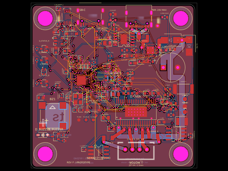 Discover something newimrishabh18/nema-23-stepper-controllerA four-layer NEMA23 stepper motor controller PCB featuring an RP2040 MCU, DRV8452 dual-phase driver, USB‑C PD power input/protection, current and temperature sensing, status LED/buzzer, and optional magnetic encoder.