AnasSarkiz/NEMA14_CH32X035G8U6
A NEMA stepper motor is shown with proposed M3 screws/spacers, four wired motor leads and splices, and a JST SHR-04V-S connector.
- Version
- 1.12.2
- License
- ISC
- Stars
- 0
docs/electrical.md
> Historical baseline document: this predates the opposite-edge v1.11.0 draft. See [current draft and blockers](opposite-edge-review.md) for current evidence.

# Electrical design review

A4988 VREF = 3.3 × 10/(39+10) = 0.6735 V; Itrip = VREF/(8 × 0.24) = 0.3508 A. The native 0.24 Ω, 1%, 125 mW resistors dissipate about 29.5 mW nominally. A deliberately expanded 3.465 V rail budget, 1% resistor bounds and a provisional 5% driver allowance estimate 0.3969 A. This is an engineering budget, not a qualified maximum: the actual driver accuracy, ground bounce and sense-track resistance must be measured. The SMF18A clamp still requires regenerative-energy testing.


## Copper review, 2026-10-07

The checked saved layout, rather than nominal JSX settings, was reviewed. Power/motor tracks were widened only when exact imported pad, via and foreign-track geometry retained at least 0.15 mm clearance. Their centerlines were retained. `artifacts/power-copper-adjustments.json` records each width change; `supplier-routing-adjustments.json` replays the complete result from the saved SES import. Ground pours have 0.20 mm clearance, 0.35 mm edge margin, and no unconnected islands. Components remain top-side assembled.

| Copper | Actual saved width / review |
| --- | --- |
| Motor outputs / sense | About 0.28–0.45 mm, including package escapes; screened at 0.40 A peak |
| PD motor supply | 0.30–0.60 mm; 0.75 A input budget, with a verified single-bridge RP2040 branch screened at 0.40 A |
| Logic supply / switching node | Widened where possible; package escapes remain as small as 0.16 mm; 0.15 A rail / 0.20 A switching budget |
| Ground | 0.16–0.45 mm tracks plus filled ground copper; parallel plane paths must be considered, rather than assuming the entire motor return flows down every ground stub |
| USB / other signals | 0.16 mm; width alone does not establish differential impedance or signal integrity |

Copper screening requires **at least 35 μm finished external copper and 17.5 μm internal copper** where applicable, on 1.6 mm FR-4, with at least 20 μm via barrel plating. These are fabrication requirements, not measurements of a manufactured PCB. IPC-2221 equations use k=0.048 externally and 0.024 internally, with a 30 °C rise screening limit. The report includes each actual segment, layer, current budget and temperature estimate. This approximate method does not model enclosure/motor heating, neck heat spreading, switching pulses, vias or ground-plane current sharing.

The largest isolated non-ground trace estimate is 5.2 °C at its assigned budget. Ground traces covered by the same-net pour are explicitly reported as parallel paths; their isolated-track estimate is not a prediction of actual plane temperature. Ground current sharing and regulator/driver temperatures remain bench checks.


## Voltage sensing correction

R_VM_H/R_VM_L is now **100 kΩ/10 kΩ**, replacing 100 kΩ/22 kΩ. It produces 1.364 V at 15 V; the worst resistor-tolerance value is 3.240 V at a 35 V review envelope. The old divider produced 3.606 V at only 20 V, before tolerance, so motor regeneration could overstress the ADC input. This change reuses JLCPCB C25804 and its unchanged native footprint. **Firmware must multiply VM_SENSE voltage by 11**, with calibration as needed. The 35 V arithmetic envelope is not approval to operate the motor bus at 35 V; the intended supply remains 15 V. Rails, TVS energy and component ratings require transient testing.

## Operation review and remaining tests

CH224K requests 15 V with CFG1/2/3 = 0/1/1; PG is active low. A supply must advertise the requested PDO. Driver ENABLE_N has a pull-up, SLEEP has a pull-down, and firmware must keep the bridge disabled until PG and measured VM are valid. Diode ORing separates host VBUS from PD while permitting logic-only USB power. USB/data ground is shared with motor power.

USB programming entry is wired: WCH ROM ISP through PC17/D+ at cold power-up on CH32; RP2040 ROM USB boot through the flash-CS boot jumper and RUN/reset. This has not been demonstrated on physical hardware. USB routes were checked for continuity and shorts, but were not impedance-qualified or accepted as a length-matched differential pair. Reported per-net copper totals contain connector/ESD branches and must not be interpreted as pair skew. Host-only, PD-only and simultaneous-cable tests, both Type-C orientations, repeated enumeration and actual flashing are required.

At first bring-up, keep the motor disconnected, power through a current-limited source, check all rails and confirm disabled outputs. Then verify 15 V PD negotiation/fallback behavior and absence of host backfeed. Measure 3.3 V ripple and load-step response (plus RP2040 1.1 V and crystal startup), flash over USB, measure both phase currents and sense offsets, and exercise stalled/accelerating/stopping motor cases while watching VM overshoot and driver/regulator temperatures. Test at the intended motor/enclosure temperature. The CH32 linear regulator dissipates roughly (14.6−3.3)×I_logic, or about 0.34 W at 30 mA; the 100 mA part rating alone is not a thermal guarantee. The RP2040 buck's switching/input loop and feedback placement require ripple/stability validation.

No motor-control firmware is present. Rear mounting remains unverified because the motor drawing dimensions only the front face. Manufacturer-level A4988 accuracy, CH224K/HT7533 electrical limits and component transient ratings remain purchasing/release checks; direct manufacturer document retrieval was blocked in this environment. Existing pin/reference and supplier evidence is recorded in `docs/sources.md`. **Manufacturing release remains blocked.**
Related Packages
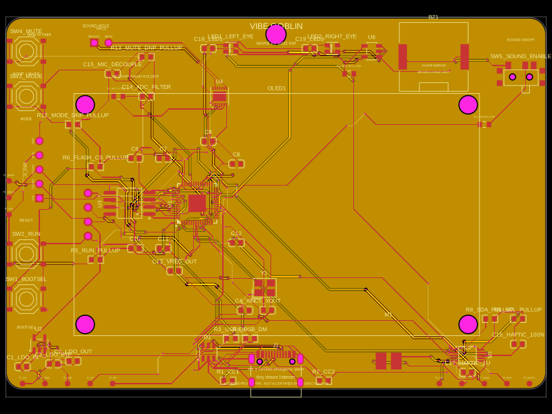 More from this authorAnasSarkiz/vibe_GoblinThese code snippets define various physical electronic components such as ICs, connectors, sensors, LEDs, and chips, specifying their pin layouts, footprint pads, silkscreen markings, courtyard outlines, and 3D CAD models for placement on PCB boards.
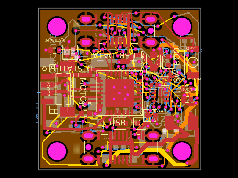 Similar packageShiboSoftwareDev/nema8-20mm-dual-usbc-stepper-controllerA compact 20 mm four-layer USB‑C stepper-controller PCB combining CH32X035 MCU control, TMC2209 motor driving, USB‑C PD/data interfaces, protection/power regulation, temperature/LED status hardware, and NEMA8 motor connectivity.
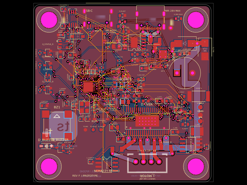 Discover something newimrishabh18/nema-23-stepper-controllerA four-layer NEMA23 stepper motor controller PCB featuring an RP2040 MCU, DRV8452 dual-phase driver, USB‑C PD power input/protection, current and temperature sensing, status LED/buzzer, and optional magnetic encoder.