0hmX/simplified-am62l-computer
This code defines components and scripts for physically representing and routing high-speed DDR memory signals, power lines, and ground planes on an 8-layer PCB with detailed pin assignments, copper pours, and precise via and trace layouts based on TI EVM reference data.
- Version
- 1.0.16
- License
- unset
- Stars
- 0
docs/AM62L_BGA_PIN_CONNECTIONS.md
# AM62L BGA pin-use report

This report describes the logical netlist in `index.circuit.tsx`. PCB routing is intentionally disabled. The AM62L package has 373 physical balls: 211 are connected to named logical nets and 162 are explicitly marked no-connect. The generated Circuit JSON confirms that no AM62L ball is left in an unspecified state.

## LPDDR4 signal balls

The mapping follows the TMDS62LEVM AM62L + Micron MT53E1G16D1ZW x16 topology. There are no DDR test points or inline series resistors.

| AM62L ball / pin | AM62L signal | Micron ball / pin | Micron signal |
|---|---|---|---|
| F4 / 94 | DDR0_DQ0 | B2 / 12 | DQ0 |
| F3 / 93 | DDR0_DQ1 | C2 / 22 | DQ1 |
| F1 / 91 | DDR0_DQ2 | E2 / 42 | DQ2 |
| E1 / 76 | DDR0_DQ3 | F2 / 52 | DQ3 |
| G4 / 105 | DDR0_DQ4 | F4 / 54 | DQ4 |
| H4 / 123 | DDR0_DQ5 | E4 / 44 | DQ5 |
| H2 / 121 | DDR0_DQ6 | C4 / 24 | DQ6 |
| H3 / 122 | DDR0_DQ7 | B4 / 14 | DQ7 |
| V4 / 275 | DDR0_DQ8 | B11 / 19 | DQ8 |
| T3 / 238 | DDR0_DQ9 | C11 / 29 | DQ9 |
| T1 / 236 | DDR0_DQ10 | E11 / 49 | DQ10 |
| U1 / 255 | DDR0_DQ11 | F11 / 59 | DQ11 |
| U4 / 257 | DDR0_DQ12 | F9 / 57 | DQ12 |
| V5 / 276 | DDR0_DQ13 | E9 / 47 | DQ13 |
| U2 / 256 | DDR0_DQ14 | C9 / 27 | DQ14 |
| W1 / 284 | DDR0_DQ15 | B9 / 17 | DQ15 |
| F2 / 92 | DDR0_DM0 | C3 / 23 | DMI0 |
| W2 / 285 | DDR0_DM1 | C10 / 28 | DMI1 |
| G1 / 103 | DDR0_DQS0 | D3 / 33 | DQS0_t |
| G2 / 104 | DDR0_DQS0_n | E3 / 43 | DQS0_c |
| V1 / 272 | DDR0_DQS1 | D10 / 38 | DQS1_t |
| V2 / 273 | DDR0_DQS1_n | E10 / 48 | DQS1_c |
| L5 / 164 | DDR0_A0 | H2 / 72 | CA0 |
| H6 / 125 | DDR0_A1 | J2 / 82 | CA1 |
| L6 / 165 | DDR0_A2 | H9 / 77 | CA2 |
| K2 / 150 | DDR0_A3 | H10 / 78 | CA3 |
| J1 / 139 | DDR0_A4 | H11 / 79 | CA4 |
| H5 / 124 | DDR0_A5 | J11 / 89 | CA5 |
| P1 / 215 | DDR0_CK0 | J8 / 86 | CK_t |
| P2 / 216 | DDR0_CK0_n | J9 / 87 | CK_c |
| K1 / 149 | DDR0_CKE0 | J4 / 84 | CKE |
| L3 / 162 | DDR0_CS0_n | H4 / 74 | CS |
| J2 / 140 | DDR0_RESET0_n | T11 / 139 | RESET_n; 10k to GND |
| M3 / 182 | DDR0_CAL0 | — | 240 ohm to GND |

The SoC DDR0_ODT0 ball L4/pin163 is intentionally NC. Micron ODT_CA G2/pin62 is independently pulled to the 1.1 V DDR rail through 2.2k. Micron ZQ A5/pin5 uses 240 ohm to GND.

## Boot, reset, clock, PMIC, UART and SD balls

| Ball / pin | Signal | Logical net / disposition |
|---|---|---|
| AB18 / 345 | PORz | SOC_PORz from 1.8 V reset gate; 22pF optional filter fitted |
| Y18 / 310 | RTC_PORz | PMIC RTC_PORz with 1.8 V pull-up |
| E16 / 87 | RESETz | Manual reset, 10k pull-up to 1.8 V |
| C16 / 55 | RESETSTATz | SD power gate input and named debug net |
| C8 / 51 | EXTINTn | PMIC nINT with 1.8 V pull-up |
| AA18 / 324 | PMIC_LPM_EN0 | PMIC MODE/STBY |
| AA22 / 326 | WKUP_I2C0_SDA | PMIC SDA, 4.7k pull-up to 1.8 V |
| AB22 / 349 | WKUP_I2C0_SCL | PMIC SCL, 4.7k pull-up to 1.8 V |
| AC18 / 368 | WKUP_OSC0_XI | 25 MHz crystal input |
| AC17 / 367 | WKUP_OSC0_XO | 25 MHz crystal output |
| F23 / 102 | BOOTMODE15 | 10k up to 1.8 V |
| F22 / 101 | BOOTMODE14 | 10k down to GND |
| G22 / 118 | BOOTMODE13 | 10k up to 1.8 V |
| G23 / 119 | BOOTMODE12 | 10k down to GND |
| C13 / 54 | UART0_TXD | UART0_TX_1V8 to fixed-direction translator |
| D13 / 68 | UART0_RXD | UART0_RX_1V8 from fixed-direction translator |
| Y2 / 300 | MMC1_CLK | SD_CLK_SOC through 0 ohm to SD_CLK |
| Y3 / 301 | MMC1_CMD | SD_CMD; 47k up to SD_IO |
| AA1 / 315 | MMC1_DAT0 | SD_DAT0; 47k up to SD_IO |
| Y4 / 302 | MMC1_DAT1 | SD_DAT1; 47k up to SD_IO |
| AA2 / 316 | MMC1_DAT2 | SD_DAT2; 47k up to SD_IO |
| AB2 / 329 | MMC1_DAT3 | SD_DAT3; 47k up to SD_IO |
| B6 / 29 | MMC1_SDCD | SD_CD_SOC through 100 ohm to card-detect net |
| D6 / 64 | MMC1_SDWP / GPIO0_123 | SD_PWR_GPIO, default-on pull-up, ANDed with RESETSTATz |
| AB19 / 346 | EXT_WAKEUP0 | Unused; 10k inactive pull-down |
| AB20 / 347 | EXT_WAKEUP1 | Unused; 10k inactive pull-down |

BOOTMODE[15:12] is `1010`: microSD primary, UART backup, 25 MHz reference.
Each of the four strap nets also has a 1 mm override/test pad (`TP_BOOT15` through `TP_BOOT12`).

## Supply and ground balls

| Rail / use | AM62L pin numbers |
|---|---|
| VDD_CORE_0V75 | 142, 143, 144, 145, 153, 155, 171, 186, 188, 206, 219, 220, 221, 229, 230 |
| VDD_RTC_0V75 | 248 |
| VDD_DDR_1V1 | 167, 184, 185, 202, 217 |
| VDD_1V8 | 109, 128, 131, 146, 173, 190, 223, 233, 246, 249 |
| VDDA_1V8, separate PMIC LDO1 rail | 154, 169 |
| VDD_3V3 | 127 |
| Switched SD_3V3 | 267 |
| SD_IO internal LDO rail | 247, 244; 3.3uF to GND |
| Independent CAP_VDDS nodes, each 1uF to GND | 110, 141, 157, 189, 260 |
| True VSS balls | 1, 2, 4, 10, 13, 16, 19, 22, 23, 24, 28, 40, 43, 46, 53, 56, 60, 77, 78, 79, 80, 81, 85, 86, 95, 96, 97, 106, 107, 108, 111, 114, 115, 116, 120, 126, 130, 132, 151, 152, 156, 166, 168, 170, 172, 174, 180, 187, 201, 203, 204, 205, 207, 218, 222, 226, 228, 231, 232, 237, 242, 243, 250, 258, 259, 261, 264, 265, 266, 268, 269, 274, 278, 279, 288, 289, 291, 293, 294, 295, 296, 299, 311, 312, 317, 325, 328, 334, 348, 350, 351, 352, 361, 364, 369, 372, 373 |
| Grounded unused analog/interface pins | 112, 113, 129, 208, 245, 262, 263, 280, 281, 282, 283, 371 |

Pin186 (VDDA_DDR_PLL0) is intentionally on 0.75 V, not 1.8 V. Pin248 (VDD_RTC) is intentionally on the 0.75 V RTC rail. UART0's VDDSHV1 pins 109 and 128 are intentionally at 1.8 V to match the translator A-side.

## Explicitly unused interface groups

- VPP pin209, reserved pin344 and LFOSC0_XO pin370 are NC.
- WKUP UART pins 297, 298, 313 and 327 are NC.
- JTAG/EMU pins 308, 309, 323, 341, 342, 343 and 366 are NC until actual pads are fitted.
- USB PHY pins 330–333 and 353–356 are NC because USB-C is power-only.
- DSI signal pins 14, 15, 17, 18, 20, 21, 41, 42, 44, 45 and 70 are NC.
- DDR4-only address/command pins A6–A13, BA0/1, BG0/1, ODT0, ACT_n, RAS_n, CAS_n and WE_n are NC in LPDDR4 mode.
- All remaining unused GPIO/peripheral balls are explicitly marked no-connect by the generated pin metadata.

## Validation boundary

The netlist and pin disposition are complete enough for schematic review, and the generated Circuit JSON reports zero errors or warnings. This is not a routed or fabrication-ready PCB. DDR routing, power planes, stackup, impedance, package delays, PDN/SI analysis, USB current-limit qualification across tolerance and temperature, and a final TI/JLC footprint review remain required before fabrication. The implemented USB-C advertisement gate is documented in `USB_C_POWER_QUALIFICATION.md`.

Primary references: TI TMDS62LEVM design package SPRCAL6D sheet 23, AM62L datasheet SPRSPA1B, AM62L hardware design guide SPRADO8A, and AM62L power-supply design guidance SLVAFW3B.
Related Packages
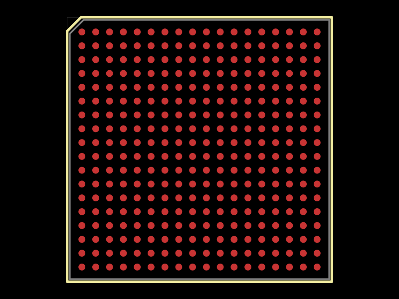 More from this author0hmX/am3352-zcz-footprintThis code defines the physical footprint and pin layout for an 18x18 ball grid array (BGA) package of a Texas Instruments AM3352 microprocessor, including pad positions and outline drawing commands for PCB design.
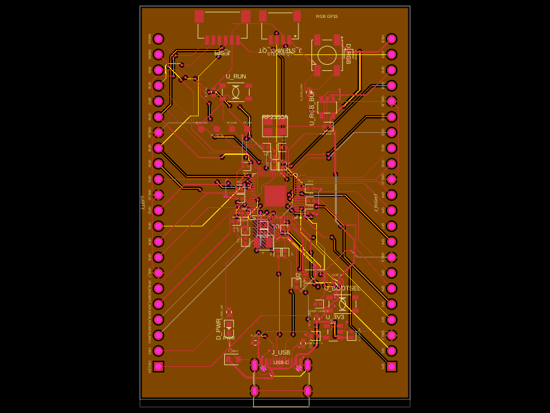 Similar packageabse/rp2350-mcu-boardThis code defines a compact, four-layer PCB hardware layout for the Raspberry Pi RP2350A microcontroller module, including the main IC, power regulation, USB-C connector, STM32-compatible headers, and associated passive components, with detailed component footprints, net connections, and copper pour zones for powering and ground references.
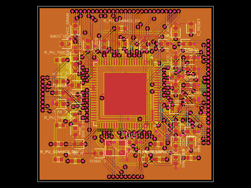 Discover something newastra/f1c100sThe code defines the physical pin layout, labels, and footprint for the F1C100S system-on-chip (SoC) component used in electronic devices.