0hmX/play-test
This code defines a compact electronic circuit with a battery, switch, three resistors, and nine LEDs arranged in three rows, with connections illustrating power, switching, and LED pathways.
- Version
- 0.0.1
- License
- unset
- Stars
- 0
matrix-2.tsx
export default () => {
  return (
    <board width="35mm" height="25mm">
      <chip
        name="BT1"
        footprint="pinrow2"
        pinLabels={{ pin1: "plus", pin2: "minus" }}
        pcbX={-13}
        pcbY={8}
        schX={-3}
        schY={2}
      />

      <chip
        name="SW1"
        footprint="pinrow2"
        pinLabels={{ pin1: "in", pin2: "out" }}
        pcbX={-3}
        pcbY={8}
        schX={0}
        schY={2}
      />

      <resistor
        name="R1"
        resistance="330"
        footprint="0603"
        pcbX={7}
        pcbY={4}
        schX={3}
        schY={1}
      />

      <resistor
        name="R2"
        resistance="330"
        footprint="0603"
        pcbX={7}
        pcbY={-4}
        schX={3}
        schY={-1}
      />

      <chip
        name="D1"
        footprint="0603"
        pinLabels={{ pin1: "a", pin2: "c" }}
        pcbX={15}
        pcbY={4}
        schX={6}
        schY={1}
      />

      <chip
        name="D2"
        footprint="0603"
        pinLabels={{ pin1: "a", pin2: "c" }}
        pcbX={15}
        pcbY={-4}
        schX={6}
        schY={-1}
      />

      {/* Power path */}
      <trace from=".BT1 > .plus" to=".SW1 > .in" />
      <trace from=".SW1 > .out" to=".R1 > .left" />
      <trace from=".SW1 > .out" to=".R2 > .left" />

      {/* LED branches */}
      <trace from=".R1 > .right" to=".D1 > .a" />
      <trace from=".R2 > .right" to=".D2 > .a" />

      {/* Ground net */}
      <trace name="GND" from=".BT1 > .minus" to=".D1 > .c" />
      <trace name="GND" from=".D1 > .c" to=".D2 > .c" />
    </board>
  )
}
Related Packages
 More from this author0hmX/am62l-lpddr4-cleanThis code defines the hardware connections and routing logic for a DDR memory interface, specifying physical signal mappings between the system-on-chip (SoC) and DDR memory components, including connections for data, address, clock, reset, and power/ground balls.
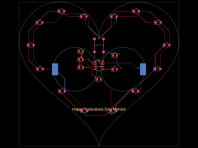 Similar packageekamresh/tscircuit_test_pcbThis code designs a battery-powered, heart-shaped circuit board featuring a NE555 timer configured as an astable multivibrator, driving 14 parallel red LEDs arranged around the heart's outline, powered by two series CR2032 coin cells, with power switching and silent silkscreen annotations.
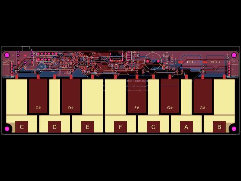 Discover something newmohan-bee/stm32-midi-keysClips rectangular ground-region geometry to fit within the board’s scaled rounded-edge outline using polygon intersection.