0hmX/dual-usb-peltier-assembly
A complete USB‑C PD Peltier controller assembly featuring an RP2040, adjustable TPS55289 buck‑boost TEC driver, 12 V fan supply, temperature-sensor inputs, USB programming, protection, status LEDs, and supporting passives/connectors.
- Version
- 0.4.7
- License
- unset
- Stars
- 0
assets/assembly/provenance.json
{
  "units": "mm",
  "pcb": {
    "source": "dist/index/circuit.json",
    "geometry": "Actual unrouted tscircuit PCB and its component placement, inside native assembly.device; supplied component OBJ models where available. Drawing-derived bodies remain approximate. DNP copper test pads appear in the PCB surface texture with no artificial component bodies.",
    "routing": "No copper routing. Wires in this assembly are external connection illustrations."
  },
  "peltier": {
    "description": "HiLetgo TEC1-12706 2-pack; the board drives one module",
    "source": "https://www.amazon.com/dp/B00M1PM7H6",
    "bodyDimensionsMm": [
      40,
      40,
      3.6
    ],
    "geometry": "Amazon listing dimensional envelope, not manufacturer CAD. Ceramic plates and core are visual approximations; lead routing, diameter and length are illustrative. Confirm purchased samples before mechanical manufacture.",
    "nativePart": "TEC_DEFAULT",
    "leadParts": [
      {
        "nativePart": "TEC_POS_LEAD",
        "boardConnector": "J_TEC",
        "pin": "pin1",
        "polarity": "positive",
        "illustrationColor": "red"
      },
      {
        "nativePart": "TEC_NEG_LEAD",
        "boardConnector": "J_TEC",
        "pin": "pin2",
        "polarity": "negative",
        "illustrationColor": "black"
      }
    ]
  },
  "officialCadAttempts": [
    {
      "part": "GCT USB4085-GF-A",
      "source": "https://gct.co/connector/usb4085",
      "cadSource": "https://www.traceparts.com/els/gct/en/api/viewer/3d?EnablePresentationMode=true&MenuAlwaysVisible=true&MergeUIMenu=true&PartNumber=USB4085-GF-A&SupplierID=GLOBAL_431202195",
      "result": "Manufacturer offers CAD through TraceParts; no downloadable mesh obtained. Board uses the exact-part EasyEDA supplier mesh, which is not claimed to be manufacturer-authored."
    },
    {
      "part": "TI TPS55289RYQR",
      "source": "https://www.ti.com/product/TPS55289",
      "cadSource": "https://vendor.ultralibrarian.com/TI/embedded/?gpn=TPS55289&package=RYQ&pin=21",
      "result": "Manufacturer-linked CAD export requires registered authorization. Use TI RYQ0021A drawing-derived 5 x 3 x 1 mm maximum-height package envelope where no supplier mesh is present.",
      "drawingSource": "https://www.ti.com/lit/pdf/MPQF641"
    },
    {
      "part": "HiLetgo DS18B20 wired probe B00M1PM55K",
      "source": "https://hiletgo.com/ProductDetail/2169579.html",
      "result": "No manufacturer CAD or selected-SKU housing drawing located. The primary product page is sparse and contains lead-color variants; the selected Amazon SKU is the authority for its cable length/color map. Housing remains an explicitly illustrative envelope."
    },
    {
      "part": "Noctua NF-A8 family CAD for selected NF-A8 PWM",
      "source": "https://www.noctua.at/en/products/nf-a8-pwm/downloads",
      "cadSource": "https://cdn.noctua.at/media/f3e65726/NF-A8_Public-CAD.zip?download=true",
      "result": "Official STEP and manufacturer usage notice downloaded and retained. Offline tessellation preserves external/mounting geometry at moderate detail; internal geometry follows the manufacturer public-model limitation. See fan.geometry for conversion/source provenance."
    }
  ],
  "assemblyLimitations": "Connection and packaging visualization only. No heatsink, cold plate, clamping mechanism or thermal interface is specified by this assembly. Do not power a bare Peltier without an appropriate hot-side thermal assembly.",
  "usbCables": {
    "description": "Two Cable Matters 201440 USB-C to USB-C USB 2.0 data / 240 W / 5 A cables, 1 m option",
    "source": "https://www.cablematters.com/pc-1532-123-usb-c-20-charging-cable-with-240w-power-delivery.aspx",
    "quantity": 2,
    "roles": [
      {
        "boardPort": "J_USB",
        "role": "PD power from 100 W USB-C charger",
        "illustrationColor": "black",
        "nativePart": "USB_PD_CABLE"
      },
      {
        "boardPort": "J_PROGRAM",
        "role": "Program/debug USB 2.0 connection to PC",
        "illustrationColor": "light gray",
        "nativePart": "USB_PROGRAM_CABLE"
      }
    ],
    "electricalRating": "Manufacturer specifies up to 48 V / 5 A power delivery, an E-Marker, and USB 2.0 data up to 480 Mbps. Both roles can use this same cable product. Board data speed is determined by its USB implementation.",
    "geometry": "Connection illustrations. Only short segments and board-side plugs are shown. Manufacturer does not publish plug/jacket CAD or dimensions; shapes and role colors are indicative, not fit-qualified geometry. Cable slack, charger end and PC end are omitted."
  },
  "nativeAssembly": {
    "source": "src/assembly/general-pd-assembly.tsx",
    "geometrySource": "src/assembly/models.ts",
    "connectorMappingSource": "src/assembly/connector-placement.ts",
    "api": "https://docs.tscircuit.com/elements/assembly-part",
    "geometry": "Native assembly.device + eleven literal CAD-only assembly.part models; no accessory PCB components, electrical ports or JLCPCB BOM entries. The fan uses official NF-A8 family CAD. Other peripheral bodies and cable routes are documented envelopes. Board-side XY points derive from real connector placements and exact supplier-footprint insertion/pin offsets. Colored cable polygons retain vendor lead colors. Cable/mating heights, plug/jacket dimensions, routes and probe housing dimensions are explicitly illustrative."
  },
  "temperatureProbes": {
    "description": "Two HiLetgo DS18B20 wired stainless probes, from the selected five-pack",
    "source": "https://www.amazon.com/dp/B00M1PM55K",
    "quantityUsed": 2,
    "cableLengthMm": 1000,
    "housingDimensionsVerified": false,
    "illustrativeHousingEnvelopeMm": {
      "diameter": 6,
      "length": 50
    },
    "housingDimensionEvidence": "The selected Amazon listing provides cable length and lead colors, but no verified metal-housing dimensions. Package dimensions and specifications for other sellers are not used as probe dimensions.",
    "wireMap": [
      {
        "pin": "pin1",
        "signal": "CTRL_3V3",
        "color": "red"
      },
      {
        "pin": "pin2",
        "signal": "HOT_SENSOR_DATA / COLD_SENSOR_DATA",
        "color": "yellow"
      },
      {
        "pin": "pin3",
        "signal": "GND",
        "color": "black"
      }
    ],
    "roles": [
      {
        "role": "HOT",
        "boardPort": "J_HOT_SENSOR",
        "nativePart": "HOT_PROBE",
        "cableNativePart": "HOT_PROBE_CABLE",
        "gpio": "GP8"
      },
      {
        "role": "COLD",
        "boardPort": "J_COLD_SENSOR",
        "nativePart": "COLD_PROBE",
        "cableNativePart": "COLD_PROBE_CABLE",
        "gpio": "GP9"
      }
    ],
    "geometry": "Native CAD-only probe parts use explicitly illustrative diameter 6 mm by length 50 mm metal cylinders, not verified seller dimensions or manufacturer CAD. Factory cable length 1 m and red VCC / yellow DATA / black GND follow the selected Amazon listing. Only short jacket paths and three colored conductor fanouts are shown. Jacket diameter 3 mm, conductor diameter 0.7 mm, wire-channel height 3 mm and routing are illustrative and not fit-qualified.",
    "placement": "HOT is shown near the upper TEC face and COLD near the opposite lower face, laterally offset so both can be inspected. These positions illustrate roles; actual thermal contact, clamps and module face orientation must be established in the physical thermal assembly."
  },
  "fan": {
    "description": "Noctua NF-A8 PWM 12 V, direct factory cable without Low-Noise Adaptor or extension",
    "source": "https://www.amazon.com/dp/B00NEMG62M",
    "manufacturerSpecifications": "https://www.noctua.at/en/products/nf-a8-pwm/specifications",
    "manufacturerSpecificationPdf": "https://cdn.noctua.at/media/800cb82a/Noctua%20NF-A8%20PWM%20Specification.pdf?download=true",
    "manufacturerWiring": "https://noctua.at/pub/media/wysiwyg/Noctua_PWM_specifications_white_paper.pdf",
    "nativePart": "FAN_DEFAULT",
    "cableNativePart": "FAN_CABLE",
    "boardConnector": "J_FAN",
    "bodyDimensionsMm": [
      80,
      80,
      25
    ],
    "bodyWithPadsDimensionsMm": [
      81,
      81,
      27
    ],
    "mountingHoleSpacingMm": 71.5,
    "dimensionsVerified": true,
    "nominalVoltageV": 12,
    "maximumInputCurrentA": 0.08,
    "boardContinuousFanBudgetA": 0.5,
    "cableLengthMm": 200,
    "includedOptionalExtensionMm": 300,
    "extensionFitted": false,
    "lowNoiseAdaptorFitted": false,
    "cableDescription": "Manufacturer 26 AWG, black mesh-sleeved four-wire factory cable with A2543-4PIN (or equivalent) plug; mates the Molex47053-1000 header.",
    "wireMap": [
      {
        "pin": "pin1",
        "signal": "GND",
        "color": "black",
        "boardConnected": true
      },
      {
        "pin": "pin2",
        "signal": "FAN_12V",
        "color": "yellow",
        "boardConnected": true
      },
      {
        "pin": "pin3",
        "signal": "TACH_NC",
        "color": "green",
        "boardConnected": false
      },
      {
        "pin": "pin4",
        "signal": "PWM_NC",
        "color": "blue",
        "boardConnected": false
      }
    ],
    "geometry": {
      "source": "Official Noctua NF-A8 family CAD, used for the selected NF-A8 PWM external and mounting dimensions; not a uniquely PWM-specific STEP.",
      "archiveUrl": "https://cdn.noctua.at/media/f3e65726/NF-A8_Public-CAD.zip?download=true",
      "downloadPage": "https://www.noctua.at/en/products/nf-a8-pwm/downloads",
      "originalStep": "src/assembly/assets/NF-A8_Public-CAD.stp",
      "sourceNotice": "src/assembly/assets/Noctua-CAD-README.txt",
      "stepSha256": "b6dbbc33922844d38642564fdabcf52d54a8769e69123471472242e18bb0e0ef",
      "derivedMesh": "src/assembly/assets/noctua-nf-a8-pwm.mesh.json",
      "conversion": {
        "tool": "occt-import-js, offline ReadStepFile",
        "linearUnit": "millimeter",
        "linearDeflectionType": "absolute_value",
        "linearDeflectionMm": 0.5,
        "angularDeflectionRadians": 0.8,
        "vertexZOffsetMm": 6.5,
        "coordinateDecimalPlaces": 4,
        "meshCount": 12,
        "triangles": 31113,
        "vertices": 30216
      },
      "appearance": "Manufacturer CAD colors retained where supplied. Uncolored rotor meshes use brown [0.26, 0.12, 0.06]; uncolored label mesh uses gray [0.12, 0.12, 0.12]. These are visualization defaults.",
      "manufacturerLimit": "Manufacturer permits visualization/integration reference. Internal impeller geometry is modified to protect IP; not for performance simulation or reproducing/manufacturing the fan."
    },
    "cableGeometry": "Illustrative plug/key and black sleeve with short four-color fanout at the plug. Contact/locator XY matches the exact supplier footprint. Mating height 6.8 mm, plug height/shape, 3.2 mm sleeve diameter, 0.7 mm conductor diameter, fan cable exit and bends are approximate. The shown sleeve centerline plus connector-exit fanout is about 200 mm; plug-interior leads are separate. Manufacturer nominal cable length does not specify its measurement endpoints or this laid-out route.",
    "placement": "Fan center [112, -92, 20] mm in an exploded connectivity view, clear of PCB, TEC and probes. This is not a mounting or thermal design; no hot-side heatsink or cooling-performance guarantee is supplied.",
    "electricalUse": "Pins 1/2 provide fixed 12 V power. Pin 3 tach and pin 4 PWM remain physically present in the plug but are NC on the board; unconnected PWM runs at full speed. Manufacturer maximum input current is not a published startup-current peak."
  }
}
Related Packages
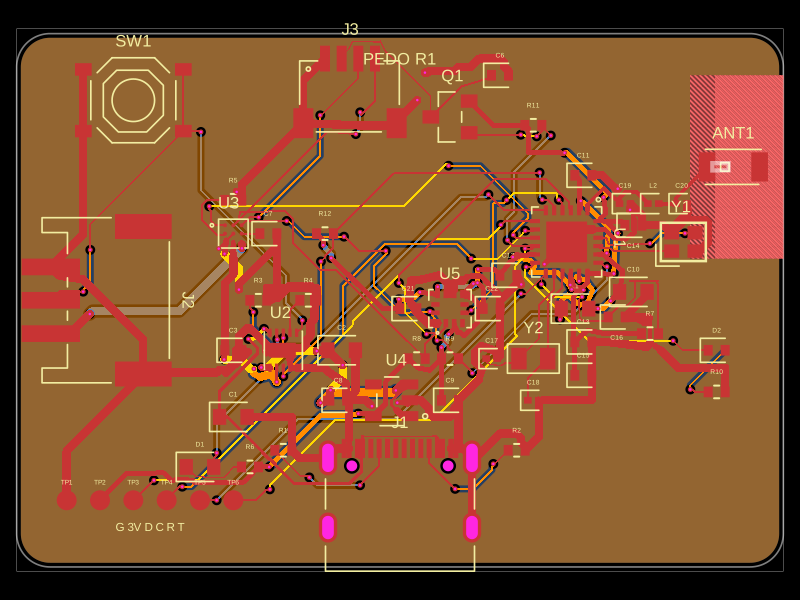 More from this author0hmX/bluetooth-pedometer-pcbThis code defines and renders a detailed electronic circuit board layout with labeled components, footprints, 3D models, and routing, suited for PCB design and manufacturing.
 Similar packageaura/diy-power-delivery-triggerThis hardware design implements a USB Type-C port with supporting power management and signal conditioning components, including a USB-C connector, a FUSB302 USB-C port controller, ESD protection diodes, a buck converter for 3.3V power regulation, an STM32 microcontroller for control and processing, an RGB LED indicator, push button, terminal block connections, and associated filtering and support components.
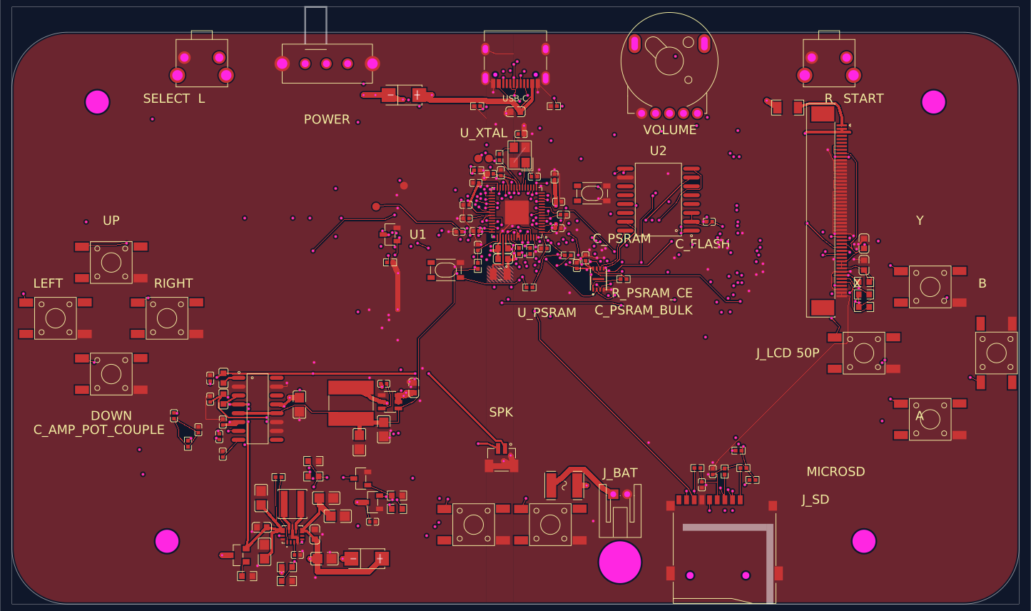 Discover something newabse/gameboy-advanceA validated four-layer Game Boy Advance-style PCB assembly centered on an RP2350 MCU, 32‑MB QSPI flash, PSRAM, USB‑C, microSD, LCD/touch connector, AA battery buck‑boost power, controls, and speaker amplifier.