vasu/blinking-led
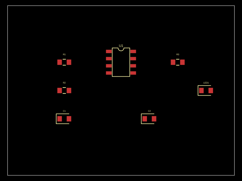
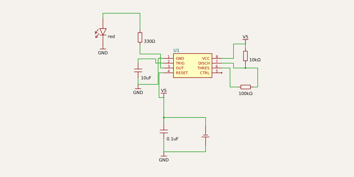
This design implements a 555 timer-based astable multivibrator circuit to generate a periodic blinking signal for an LED powered by a 5V battery.
- Version
- 0.0.1
- License
- unset
- Stars
- 0
index.tsx
PCB
Schematic
export default () => {
  return (
    <board width="40mm" height="30mm" routingDisabled>
      {/* 555 Timer IC (astable configuration) */}
      <chip
        name="U1"
        footprint="soic8"
        pinLabels={{
          pin1: "GND",
          pin2: "TRIG",
          pin3: "OUT",
          pin4: "RESET",
          pin5: "CTRL",
          pin6: "THRES",
          pin7: "DISCH",
          pin8: "VCC",
        }}
        connections={{
          VCC: "net.V5",
          GND: "net.GND",
          RESET: "net.V5",
          TRIG: "R2.pin2",
          THRES: "R2.pin2",
          DISCH: "R1.pin2",
          OUT: "R3.pos",
        }}
        pcbX={0}
        pcbY={5}
      />

      {/* Timing resistors */}
      <resistor
        name="R1"
        resistance="10k"
        footprint="0603"
        pcbX={-10}
        pcbY={5}
        connections={{ pin1: "net.V5" }}
      />
      <resistor
        name="R2"
        resistance="100k"
        footprint="0603"
        pcbX={-10}
        pcbY={0}
        connections={{ pin1: "R1.pin2" }}
      />

      {/* Timing capacitor (across CTRL/THRES node to GND) */}
      <capacitor
        name="C1"
        capacitance="10uF"
        footprint="0603"
        pcbX={-10}
        pcbY={-5}
        connections={{ pos: "R2.pin2", neg: "net.GND" }}
      />

      {/* Decoupling capacitor for the 555 */}
      <capacitor
        name="C2"
        capacitance="0.1uF"
        footprint="0603"
        pcbX={5}
        pcbY={-5}
        connections={{ pos: "net.V5", neg: "net.GND" }}
      />

      {/* Current-limiting resistor for LED */}
      <resistor
        name="R3"
        resistance="330"
        footprint="0603"
        pcbX={10}
        pcbY={5}
      />

      {/* Blinking LED */}
      <led
        name="LED1"
        color="red"
        footprint="0603"
        pcbX={15}
        pcbY={0}
        connections={{ pos: "R3.neg", neg: "net.GND" }}
      />

      {/* Power net */}
      <battery
  name="BAT1"
  voltage="5V"
  capacity="2500mAh"
  pcbX={0}
  pcbY={-12}
  connections={{ pos: "net.V5", neg: "net.GND" }}
/>
    </board>
  )
}