tscircuit/motor-controller
This code defines a compact hardware layout with multiple integrated components such as microcontrollers, power regulators, sensors, connectors, and passive elements, all arranged on a PCB for a versatile electronic device.
- Version
- 1.0.14
- License
- unset
- Stars
- 0
Esp32Section.tsx
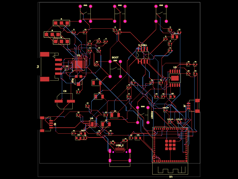
PCB
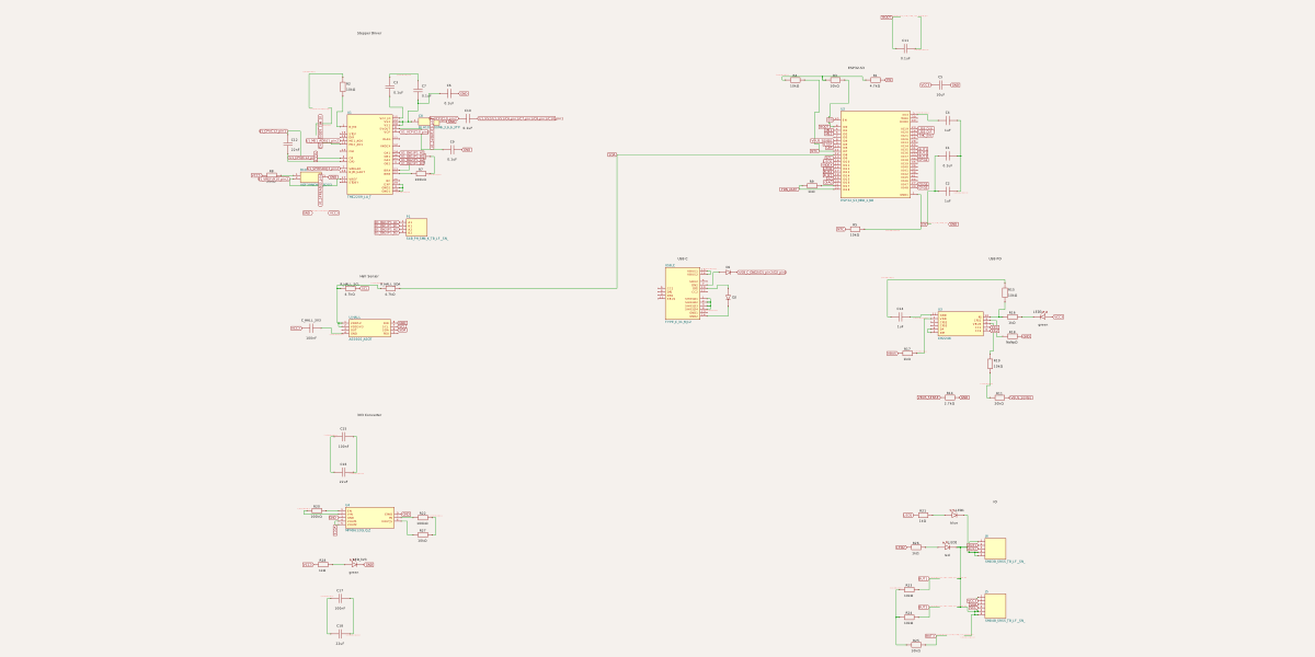
Schematic
import { ESP32_S3_MINI_1_N8 } from "./imports/ESP32_S3_MINI_1_N8";

export const Esp32Section = () => (
	<group pcbX={10} pcbY={16} schX={10} schY={8}>
		<schematictext text="ESP32-S3" schY={5} fontSize={0.5} />
		<ESP32_S3_MINI_1_N8
			name="U2"
			pcbX={12}
			pcbY={-43}
			pcbRotation={180}
			schWidth={4}
			schPinArrangement={{
				leftSide: {
					direction: "top-to-bottom",
					pins: [
						"EN",
						"IO0",
						"IO1",
						"IO2",
						"IO3",
						"IO4",
						"IO5",
						"IO6",
						"IO7",
						"IO8",
						"IO9",
						"IO10",
						"IO11",
						"IO12",
						"IO13",
						"IO14",
						"IO15",
						"IO16",
						"IO17",
						"IO18",
					],
				},
				rightSide: {
					direction: "top-to-bottom",
					pins: [
						"3V3",
						"TXD0",
						"RXD0",
						"IO19",
						"IO20",
						"IO21",
						"IO26",
						"IO33",
						"IO34",
						"IO35",
						"IO36",
						"IO37",
						"IO38",
						"IO39",
						"IO40",
						"IO41",
						"IO42",
						"IO45",
						"IO46",
						"IO47",
						"IO48",
						"GND1",
					],
				},
			}}
			connections={{
				GND1: "net.GND",
				GND2: "net.GND",
				GND3: "net.GND",
				GND4: "net.GND",
				GND5: "net.GND",
				GND6: "net.GND",
				GND7: "net.GND",
				GND8: "net.GND",
				GND9: "net.GND",
				GND10: "net.GND",
				GND11: "net.GND",
				GND12: "net.GND",
				GND13: "net.GND",
				GND14: "net.GND",
				GND15: "net.GND",
				GND16: "net.GND",
				GND17: "net.GND",
				GND18: "net.GND",
				GND19: "net.GND",
				GND20: "net.GND",
				GND21: "net.GND",
				GND22: "net.GND",
				GND23: "net.GND",
				GND24: "net.GND",
				GND25: "net.GND",
				GND26: "net.GND",
				GND27: "net.GND",
				GND28: "net.GND",
				GND29: "net.GND",
				GND30: "net.GND",
				GND31: "net.GND",
				GND32: "net.GND",
				"3V3": "net.VCC3",
				EN: "net.EN",
				IO0: "net.BOOT",
				IO1: "net.MS1",
				IO2: "net.MS2",
				IO4: "net.VBUS_SENSE",
				IO5: "net.STEP",
				IO6: "net.DIR",
				IO7: "net.NTC",
				IO8: "net.SDA",
				IO9: "net.SCL",
				IO10: "net.LED1",
				IO11: "net.INDEX",
				IO12: "net.LED2",
				IO13: "net.AUX2",
				IO14: "net.AUX1",
				IO15: "net.PG",
				IO16: "net.DIAG",
				IO17: "R9.pin2",
				IO18: "net.PDN_UART",
				IO19: "net.USB_D_N",
				IO20: "net.USB_D_P",
				IO21: "net.TMC_EN",
				IO35: "net.BUT1",
				IO36: "net.BUT2",
				IO37: "net.BUT3",
				IO38: "net.CFG1",
				IO47: "net.CFG3",
				IO48: "net.CFG2",
			}}
		/>
		<resistor
			name="R1"
			resistance="4.7k"
			footprint="0402"
			pcbX={10}
			pcbY={3}
			connections={{
				pin1: "net.VCC3",
				pin2: "net.EN",
			}}
		/>
		<resistor
			name="R3"
			resistance="10k"
			footprint="0402"
			pcbX={-12}
			pcbY={7}
			connections={{
				pin1: "net.VCC3",
				pin2: "net.BOOT",
			}}
		/>
		<resistor
			name="R4"
			resistance="10k"
			footprint="0402"
			pcbX={-6}
			pcbY={-18}
			connections={{
				pin1: "net.VCC3",
				pin2: "net.NTC",
			}}
		/>
		<resistor
			name="R5"
			resistance="10k"
			footprint="0402"
			pcbX={-6}
			pcbY={-22}
			connections={{
				pin1: "net.NTC",
				pin2: "net.GND",
			}}
		/>
		<resistor
			name="R9"
			resistance="1k"
			footprint="0402"
			pcbX={-4}
			pcbY={-16}
			connections={{
				pin1: "net.PDN_UART",
				pin2: "U2.IO17",
			}}
		/>
		<capacitor
			name="C1"
			capacitance="0.1uF"
			footprint="0402"
			pcbX={12}
			pcbY={-2}
			connections={{
				pin1: "net.EN",
				pin2: "net.GND",
			}}
		/>
		<capacitor
			name="C2"
			capacitance="1uF"
			footprint="0402"
			pcbX={12}
			pcbY={1}
			connections={{
				pin1: "net.EN",
				pin2: "net.GND",
			}}
		/>
		<capacitor
			name="C4"
			capacitance="1uF"
			footprint="0402"
			pcbX={12}
			pcbY={7}
			connections={{
				pin1: "net.VCC3",
				pin2: "net.GND",
			}}
		/>
		<capacitor
			name="C5"
			capacitance="10uF"
			footprint="0805"
			pcbX={14}
			pcbY={4}
			connections={{
				pin1: "net.VCC3",
				pin2: "net.GND",
			}}
		/>
		<capacitor
			name="C11"
			capacitance="0.1uF"
			footprint="0402"
			pcbX={-20}
			pcbY={-8}
			connections={{
				pin1: "net.BOOT",
				pin2: "net.GND",
			}}
		/>
		<silkscreentext text="RESET" pcbX={4} pcbY={-30} pcbRotation={90} />
		<pushbutton
			name="SW4"
			footprint="pushbutton"
			pcbX={0}
			pcbY={-30}
			connections={{
				pin1: "net.EN",
				pin2: "net.GND",
			}}
		/>
		<silkscreentext text="BOOT" pcbX={-12} pcbY={-5} />
		<pushbutton
			name="SW5"
			footprint="pushbutton"
			pcbX={-12}
			pcbY={-10}
			connections={{
				pin1: "net.BOOT",
				pin2: "net.GND",
			}}
		/>
	</group>
);