tscircuit/dataset-srj12-bus-routing
The code defines electronic circuit diagrams featuring PCB layouts with USB-C, HDMI, and general-purpose chips, connecting their pins with traces, component footprints, and annotations for hardware design.
- Version
- 1.0.6
- License
- unset
- Stars
- 0
circuits/sample004/sample004.circuit.tsx
PCB

Schematic

import { USBC } from "../../imports/USBC"

export default () => (
  <board width="30mm" height="36mm" routingDisabled>
    <chip
      name="U1"
      footprint="qfn32"
      doNotPlace
      pcbX={0}
      pcbY={12}
      pinLabels={{
        pin16: "BUS_09",
        pin17: "BUS_00",
        pin18: "BUS_01",
        pin19: "BUS_02",
        pin20: "VBUS_IN",
        pin21: "BUS_04",
        pin22: "BUS_05",
        pin23: "GND",
        pin24: "BUS_07",
        pin25: "BUS_08",
        pin27: "BUS_10",
      }}
      pinAttributes={{
        BUS_00: { mustBeConnected: true },
        BUS_01: { mustBeConnected: true },
        BUS_02: { mustBeConnected: true },
        VBUS_IN: { requiresPower: true, mustBeConnected: true },
        BUS_04: { mustBeConnected: true },
        BUS_05: { mustBeConnected: true },
        GND: { requiresGround: true, mustBeConnected: true },
        BUS_07: { mustBeConnected: true },
        BUS_08: { mustBeConnected: true },
        BUS_09: { mustBeConnected: true },
        BUS_10: { mustBeConnected: true },
      }}
    />

    <USBC name="USBC1" pcbRotation={90} pcbX={11} pcbY={-8} />

    <capacitor name="C2" capacitance="1uF" footprint="0603" doNotPlace pcbX={3.7} pcbY={4} />
    <resistor name="R3" resistance="100" footprint="0402" doNotPlace pcbX={6} pcbY={0} />
    <capacitor name="C4" capacitance="22nF" pcbRotation={90} footprint="0603" doNotPlace pcbX={6} pcbY={14.0} />
    <resistor name="R4" resistance="47k" footprint="0603" doNotPlace pcbX={8.2} pcbY={3.6} />

    <trace from=".USBC1 > .DP1" to=".U1 > .pin25" />
    <trace from=".USBC1 > .DP2" to=".U1 > .pin26" />

  </board>
)
Related Packages
 More from this authortscircuit/autorouting-dataset-01This code manages the hardware and electronic components for circuit design and PCB layout, defining components like resistors, capacitors, transistors, connectors, and footprints, and providing tools for component placement, PCB topology, and electrical connections.
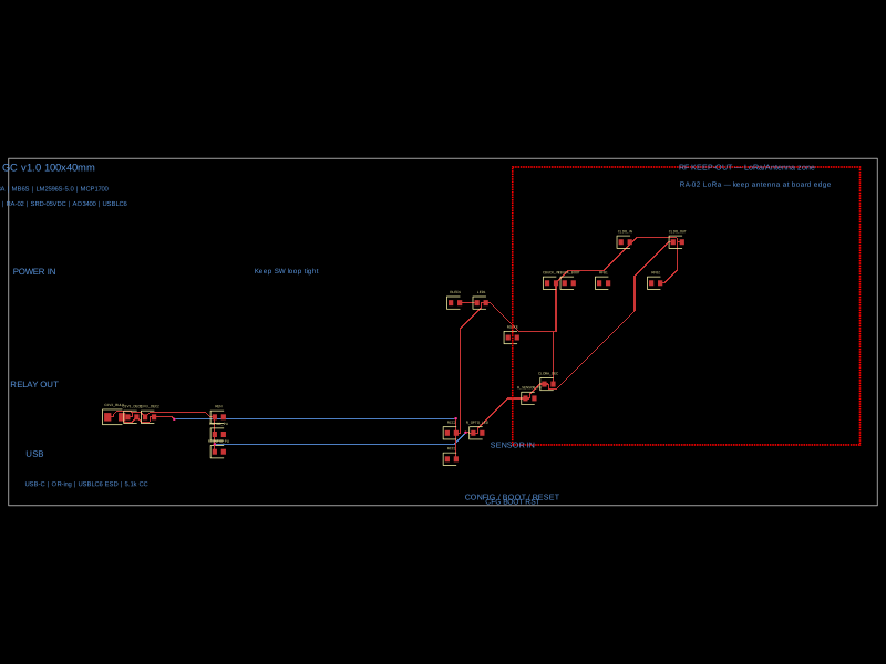 Similar packagejaiume1973/EZ-GateThe code defines a PCB layout featuring key hardware components such as a microcontroller (ESP32-S3), LoRa radio module, power regulation circuitry including buck converters and LDOs, USB-C connector, relays, sensors, buttons, and status LEDs, with traces connecting these components on a 75mm by 55mm board.
 Discover something newimrishabh18/fitness_watchThis circuit integrates an ESP-12E microcontroller with various sensors, relays, and power management components, including an AO3400A transistor for switching loads, to enable wireless control and sensing functions.