tinsangbeeping/my_led_testing
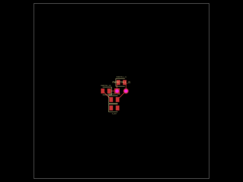
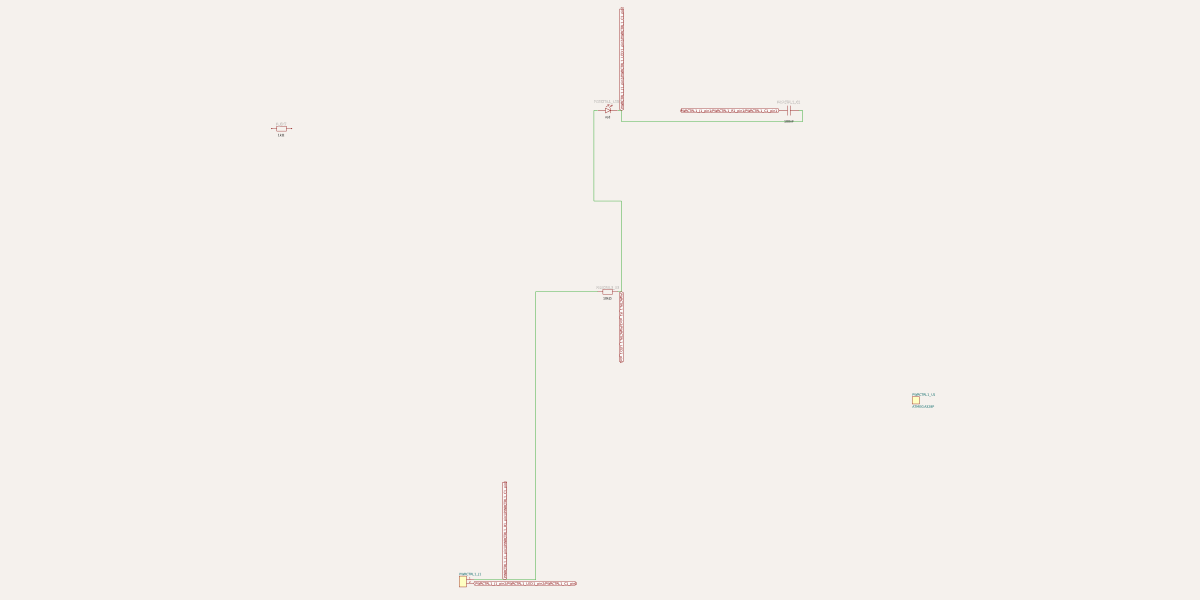
This code defines a React component that creates an electronic module with an 8-pin microcontroller (like ATMEGA328P) connected to an external 2-pin header, including an internal signal path with a resistor and LED for visual indication, plus optional decoupling capacitor.
- Version
- 0.0.1
- License
- unset
- Stars
- 0
index.tsx
PCB
Schematic
import React from "react"

type ChipWithLedSignalProps = {
  /** Instance name prefix so you can reference parts from parent traces */
  name?: string

  /** Where the block appears on the schematic */
  schX?: number
  schY?: number

  /** Pick any 8-pin part; example uses ATMEGA328P just like you showed */
  manufacturerPartNumber?: string

  /** LED / R values */
  ledColor?: "red" | "green" | "blue" | "yellow" | "white"
  ledFootprint?: string
  resistorValue?: string
  resistorFootprint?: string
  decouplingCap?: string
  capFootprint?: string
}

/**
 * A reusable “block”:
 * - Exposes two named external pins via a 2-pin header: SIGNAL and GND
 * - Internally closes the loop: SIGNAL -> R -> LED -> GND
 * - Connects SIGNAL/GND to the chip (pin1=SIGNAL, pin8=GND)
 * - Leaves chip pins 2..7 free for the parent circuit to wire
 */
export function ChipWithLedSignal({
  name = "chip_w_led_signal",
  schX = 0,
  schY = 0,
  manufacturerPartNumber = "ATMEGA328P",
  ledColor = "red",
  ledFootprint = "0805",
  resistorValue = "10k",
  resistorFootprint = "0805",
  decouplingCap = "100nF",
  capFootprint = "0805",
}: ChipWithLedSignalProps) {
  const U1 = `${name}_U1`
  const R1 = `${name}_R1`
  const LED1 = `${name}_LED1`
  const C1 = `${name}_C1`
  const J1 = `${name}_J1`

  return (
    <>
      {/* External 2-pin interface for the block */}
      <pinheader
        name={J1}
        pinCount={2}
        schX={schX + 10}
        schY={schY + 10}
        // If your editor supports pin labels, this is the intent:
        // pinLabels={["SIGNAL", "GND"]}
      />

      {/* The chip inside the block (8-pin example) */}
      <chip
        name={U1}
        manufacturerPartNumber={manufacturerPartNumber}
        schX={schX + 35}
        schY={schY + 20}
      />

      {/* Indicator path: SIGNAL -> R -> LED -> GND */}
      <resistor
        name={R1}
        resistance={resistorValue}
        footprint={resistorFootprint}
        schX={schX + 18}
        schY={schY + 26}
      />
      <led
        name={LED1}
        color={ledColor}
        footprint={ledFootprint}
        schX={schX + 18}
        schY={schY + 36}
      />

      {/* Optional decoupling cap between SIGNAL and GND (acts like VCC/GND here) */}
      <capacitor
        name={C1}
        capacitance={decouplingCap}
        footprint={capFootprint}
        schX={schX + 28}
        schY={schY + 36}
      />

      {/* ====== Internal wiring (closed loop + chip power pins) ====== */}

      {/* Bring SIGNAL into the block (J1 pin1) and feed chip pin1 */}
      <trace from={`.${J1} > .pin1`} to={`.${U1} > .pin1`} />

      {/* Bring GND into the block (J1 pin2) and feed chip pin8 */}
      <trace from={`.${J1} > .pin2`} to={`.${U1} > .pin8`} />

      {/* SIGNAL -> R -> LED -> GND */}
      <trace from={`.${J1} > .pin1`} to={`.${R1} > .pin1`} />
      <trace from={`.${R1} > .pin2`} to={`.${LED1} > .anode`} />
      <trace from={`.${LED1} > .cathode`} to={`.${J1} > .pin2`} />

      {/* Decoupling cap between SIGNAL and GND */}
      <trace from={`.${J1} > .pin1`} to={`.${C1} > .pin1`} />
      <trace from={`.${C1} > .pin2`} to={`.${J1} > .pin2`} />
    </>
  )
}

/** Example parent file: place the block and then wire to its *remaining* chip pins 2..7 */
export default function ParentCircuit() {
  return (
    <board width="50mm" height="50mm">
      <ChipWithLedSignal name="PWRCTRL1" schX={5} schY={5} />

      {/* Example: parent connects to the remaining pins (2..7) on the internal chip */}
      <resistor name="R_EXT" resistance="1k" footprint="0805" schX={5} schY={40} />

      {/* You can reference the internal chip by its stable generated name: PWRCTRL1_U1 */}
      <trace from=".R_EXT > .pin1" to=".PWRCTRL1_U1 > .pin2" />
      <trace from=".R_EXT > .pin2" to=".PWRCTRL1_U1 > .pin3" />

      {/* And you can also connect to the block’s SIGNAL/GND header if desired */}
      <trace from=".PWRCTRL1_J1 > .pin1" to=".PWRCTRL1_U1 > .pin4" />
    </board>
  )
}