tinsangbeeping/my_led_testing
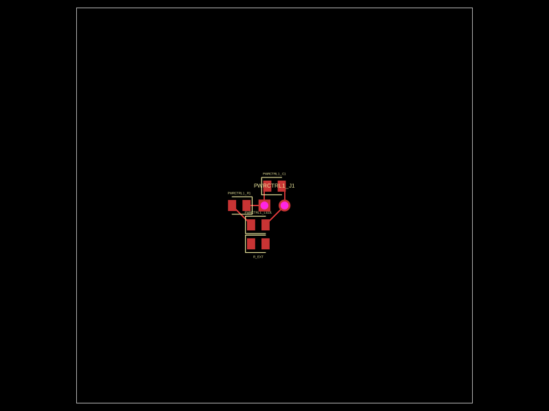
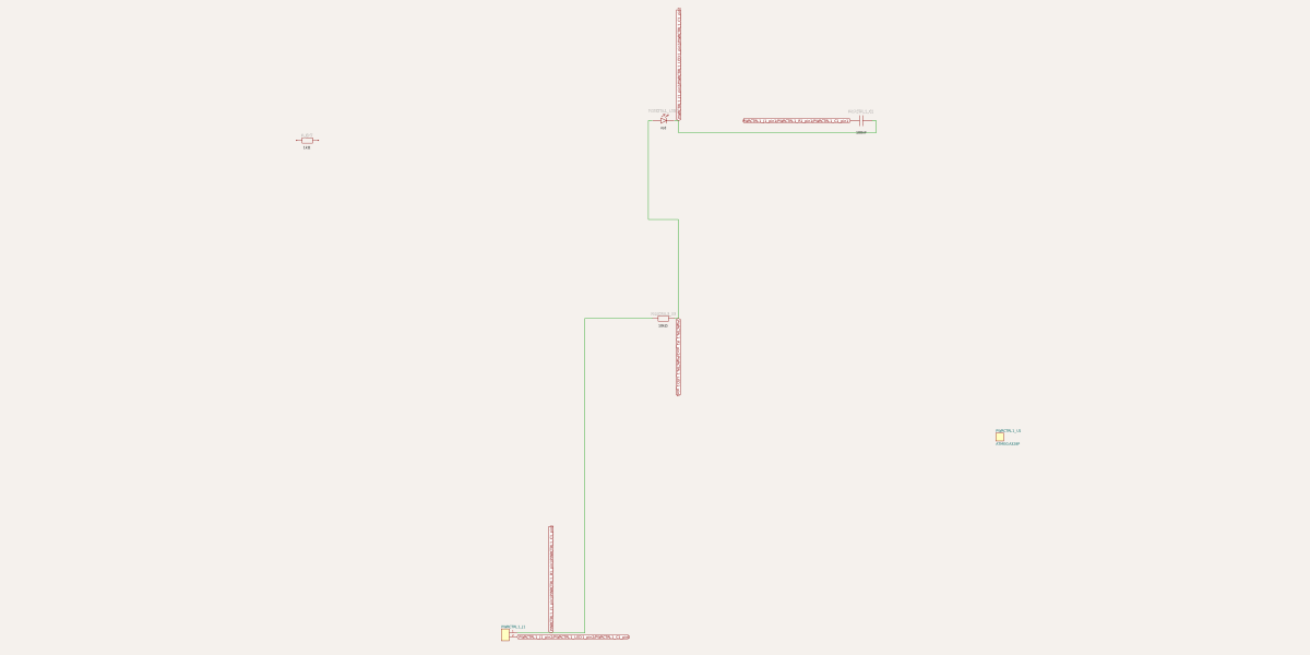
This code defines a React component that creates an electronic module with an 8-pin microcontroller (like ATMEGA328P) connected to an external 2-pin header, including an internal signal path with a resistor and LED for visual indication, plus optional decoupling capacitor.
- Version
- 0.0.1
- License
- unset
- Stars
- 0
dist/index.js
PCB
Schematic
import { jsxs, jsx, Fragment } from 'react/jsx-runtime';

/**
 * A reusable “block”:
 * - Exposes two named external pins via a 2-pin header: SIGNAL and GND
 * - Internally closes the loop: SIGNAL -> R -> LED -> GND
 * - Connects SIGNAL/GND to the chip (pin1=SIGNAL, pin8=GND)
 * - Leaves chip pins 2..7 free for the parent circuit to wire
 */
function ChipWithLedSignal({ name = "chip_w_led_signal", schX = 0, schY = 0, manufacturerPartNumber = "ATMEGA328P", ledColor = "red", ledFootprint = "0805", resistorValue = "10k", resistorFootprint = "0805", decouplingCap = "100nF", capFootprint = "0805", }) {
    const U1 = `${name}_U1`;
    const R1 = `${name}_R1`;
    const LED1 = `${name}_LED1`;
    const C1 = `${name}_C1`;
    const J1 = `${name}_J1`;
    return (jsxs(Fragment, { children: [jsx("pinheader", { name: J1, pinCount: 2, schX: schX + 10, schY: schY + 10 }), jsx("chip", { name: U1, manufacturerPartNumber: manufacturerPartNumber, schX: schX + 35, schY: schY + 20 }), jsx("resistor", { name: R1, resistance: resistorValue, footprint: resistorFootprint, schX: schX + 18, schY: schY + 26 }), jsx("led", { name: LED1, color: ledColor, footprint: ledFootprint, schX: schX + 18, schY: schY + 36 }), jsx("capacitor", { name: C1, capacitance: decouplingCap, footprint: capFootprint, schX: schX + 28, schY: schY + 36 }), jsx("trace", { from: `.${J1} > .pin1`, to: `.${U1} > .pin1` }), jsx("trace", { from: `.${J1} > .pin2`, to: `.${U1} > .pin8` }), jsx("trace", { from: `.${J1} > .pin1`, to: `.${R1} > .pin1` }), jsx("trace", { from: `.${R1} > .pin2`, to: `.${LED1} > .anode` }), jsx("trace", { from: `.${LED1} > .cathode`, to: `.${J1} > .pin2` }), jsx("trace", { from: `.${J1} > .pin1`, to: `.${C1} > .pin1` }), jsx("trace", { from: `.${C1} > .pin2`, to: `.${J1} > .pin2` })] }));
}
/** Example parent file: place the block and then wire to its *remaining* chip pins 2..7 */
function ParentCircuit() {
    return (jsxs("board", { width: "50mm", height: "50mm", children: [jsx(ChipWithLedSignal, { name: "PWRCTRL1", schX: 5, schY: 5 }), jsx("resistor", { name: "R_EXT", resistance: "1k", footprint: "0805", schX: 5, schY: 40 }), jsx("trace", { from: ".R_EXT > .pin1", to: ".PWRCTRL1_U1 > .pin2" }), jsx("trace", { from: ".R_EXT > .pin2", to: ".PWRCTRL1_U1 > .pin3" }), jsx("trace", { from: ".PWRCTRL1_J1 > .pin1", to: ".PWRCTRL1_U1 > .pin4" })] }));
}

export { ChipWithLedSignal, ParentCircuit as default };