tinsangbeeping/my_led_testing
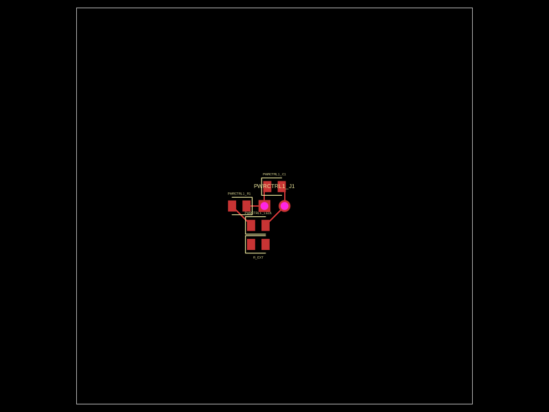
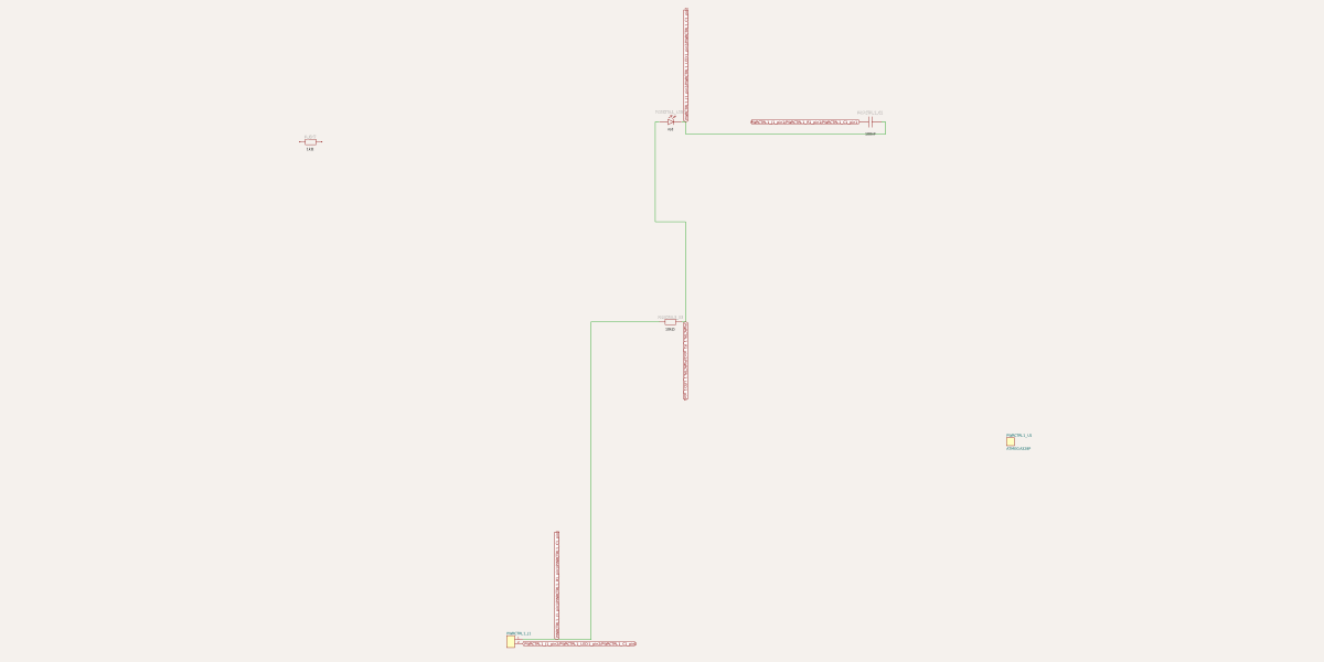
This code defines a React component that creates an electronic module with an 8-pin microcontroller (like ATMEGA328P) connected to an external 2-pin header, including an internal signal path with a resistor and LED for visual indication, plus optional decoupling capacitor.
- Version
- 0.0.1
- License
- unset
- Stars
- 0
LedSeriesBlock.tsx
PCB
Schematic
import React from "react"

type LedSeriesBlockProps = {
  name: string
  schX?: number
  schY?: number
  resistorValue?: string
}

export default function LedSeriesBlock({
  name,
  schX = 0,
  schY = 0,
  resistorValue = "330",
}: LedSeriesBlockProps) {
  return (
    <subcircuit name={name}>
      <port name="SIGNAL" schX={schX + 0} schY={schY} direction="left" />
      <port name="GND" schX={schX + 12} schY={schY} direction="right" />

      <resistor name="R1" resistance={resistorValue} footprint="0805" schX={schX + 3} schY={schY} />
      <led name="LED1" color="red" footprint="0805" schX={schX + 8} schY={schY} />

      <trace from=".SIGNAL" to=".R1 > .pin1" />
      <trace from=".R1 > .pin2" to=".LED1 > .anode" />
      <trace from=".LED1 > .cathode" to=".GND" />
    </subcircuit>
  )
}