tinsangbeeping/ledtest3
This code defines a 10mm x 10mm electronic board featuring a 1kΩ resistor and a 1000pF capacitor connected between their respective pins.
- Version
- 0.0.1
- License
- unset
- Stars
- 0
index.tsx
PCB
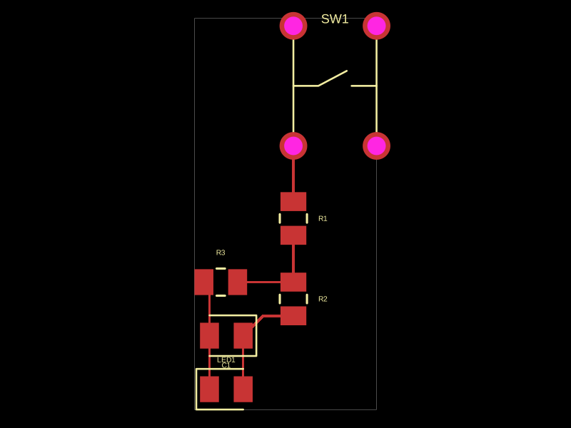
Schematic
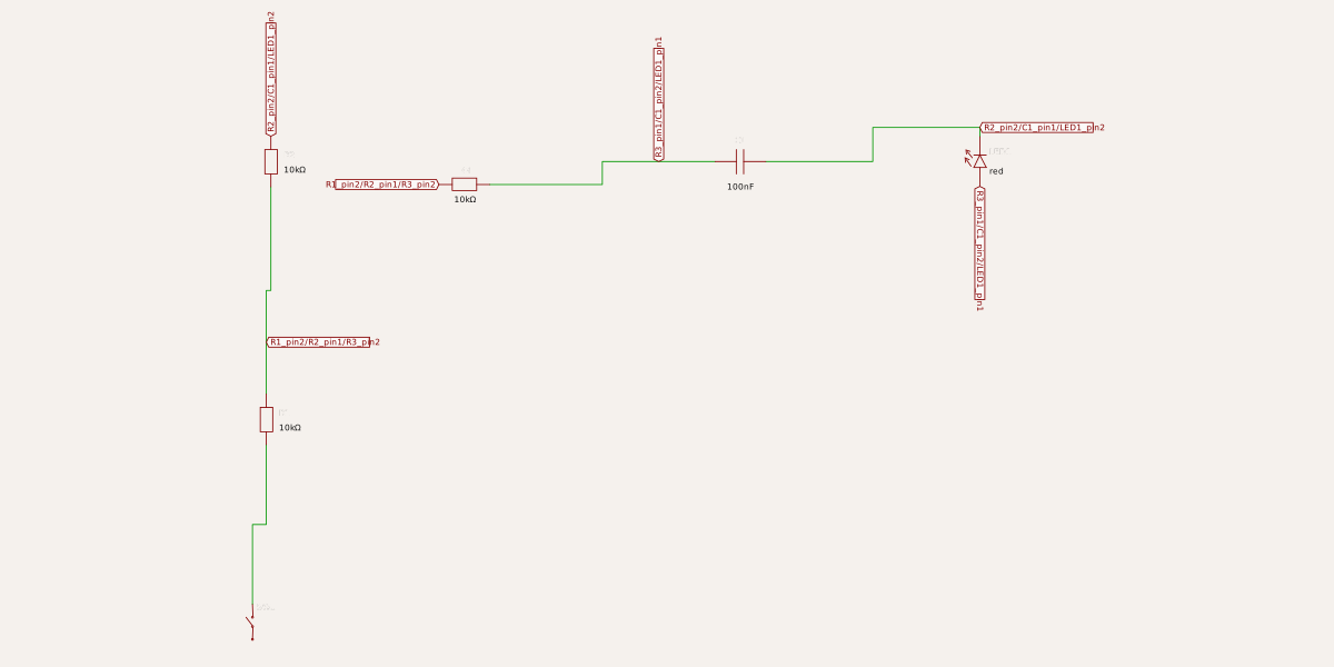
export const ports = ["power", "signal", "out"] as const

export function Led_cor_2(props: { name: string; schX?: number; schY?: number }) {
  const x = props.schX ?? 0
  const y = props.schY ?? 0

  return (
    <subcircuit name={props.name}>
    {/* // editorSchX={6} */}
    {/* // editorSchY={88} */}
    <resistor
      name="R1"
      resistance="10k"
      footprint="0805"
      schX={x + 0.3}
      schY={y + 4.4}
      schRotation="90deg"
    />
    {/* // editorSchX={8} */}
    {/* // editorSchY={200} */}
    <resistor
      name="R2"
      resistance="10k"
      footprint="0805"
      schX={x + 0.4}
      schY={y + 10}
      schRotation="90deg"
    />
    {/* // editorSchX={92} */}
    {/* // editorSchY={190} */}
    <resistor
      name="R3"
      resistance="10k"
      footprint="0805"
      schX={x + 4.6}
      schY={y + 9.5}
      schRotation="180deg"
    />
    {/* // editorSchX={212} */}
    {/* // editorSchY={200} */}
    <capacitor
      name="C1"
      capacitance="100nF"
      footprint="0805"
      schX={x + 10.6}
      schY={y + 10}
      schRotation="180deg"
    />
    {/* // editorSchX={316} */}
    {/* // editorSchY={200} */}
    <led
      name="LED1"
      color="red"
      footprint="0805"
      schX={x + 15.8}
      schY={y + 10}
      schRotation="90deg"
    />
    {/* // editorSchX={0} */}
    {/* // editorSchY={0} */}
    <switch
      name="SW1"
      type="spst"
      footprint="pushbutton"
      schX={x + 0}
      schY={y + 0}
      schRotation="90deg"
    />
    <port
      name="power"
      schX={x + 1.2}
      schY={y + 0}
    />
    <port
      name="signal"
      schX={x + 11.8}
      schY={y + 10.6}
    />
    <port
      name="out"
      schX={x + 1.6}
      schY={y + 11.2}
    />
    <trace from=".C1 > .pin2" to=".R3 > .pin1" />
    <trace from=".C1 > .pin2" to=".signal > .port" />
    <trace from=".LED1 > .anode" to=".C1 > .pin2" />
    <trace from=".LED1 > .cathode" to=".C1 > .pin1" />
    <trace from=".R1 > .pin1" to=".SW1 > .pin2" />
    <trace from=".R1 > .pin2" to=".R2 > .pin1" />
    <trace from=".R2 > .pin1" to=".R3 > .pin2" />
    <trace from=".R2 > .pin2" to=".C1 > .pin1" />
    <trace from=".R2 > .pin2" to=".out > .port" />
    <trace from=".SW1 > .pin1" to=".power > .port" />
    </subcircuit>
  )
}