techmannih/museview
A 50×35 mm USB‑C 5 V camera board combining an ESP32‑S3 module, M0031 parallel camera connector, buck/LDO power rails, USB/ESD protection, controls, status LED, and passives.
- Version
- 0.1.18
- License
- unset
- Stars
- 1
docs/bring-up.md
# Bring-up

Use a prototype first. Automated CAD checks cannot confirm soldering, rail startup or camera behavior.

1. Inspect J1/J2 alignment, regulator and diode orientation, bridge-free FPC lands and the module ground pad. With power off, check for hard shorts from 5 V, VDD_IO, CAM_2V8 and CAM_1V3 to GND. Capacitor charging is not a DC short.
2. Leave the camera unplugged. Apply current-limited 5.0 V with a conservative initial limit; if the ESP repeatedly brownouts, inspect rather than assuming normal startup. Verify TP5 near the input voltage, TP3 nominal 3.192 V, TP6 nominal 2.8 V and TP7 nominal 1.296 V. Require TP7/CAM_1V3 to stay within 1.24–1.36 V during steady operation, including ripple and measurement uncertainty; capture startup/unplug waveforms separately against sequencing requirements. Reject a camera core voltage outside 1.24–1.36 V or shared I/O above 3.3 V.
3. Verify EN rises after supply startup and RESET pulls it low. Hold BOOT, tap RESET, release BOOT; verify native USB ROM enumeration. Test both Type-C plug orientations. UART0 pads are 3.2 V logic; never connect an RS-232 level interface.
4. Build and flash `firmware/`. Confirm 16 MB flash and 8 MB octal PSRAM are detected. ASK is active low GPIO16, LED active high GPIO17. JTAG test pads correspond to GPIO39–42; native USB Serial/JTAG is also available.
5. Record the exact-flex checks in `camera-mating.md` before first-prototype release. Remove power before fitting the camera. Verify exact M0031 flex orientation and pin-1 alignment, close the latch, support the camera mechanically. Do not use a similarly shaped module on appearance alone.
6. With oscilloscope probes at the camera connector, capture all three rails, RESET and PWDN during power-up and unplug/replug. Check no damaging back-power or input excursion occurs. Verify camera identity through SCCB and one JPEG capture before sustained operation.
7. Exercise ASK, repeat capture, Wi-Fi transmission and reconnect. Measure supply current, minimum MCU voltage, rail ripple, regulator temperature and USB behavior with the intended cable/source. Complete the release-check worksheet with measurements and serial numbers.

If firmware cannot detect the camera, first check flex orientation, RESET/PWDN, XCLK, the 2.8 V analog rail and CAM_1V3 (1.296 V nominal), then SDA/SCL. Do not adjust the core outside the 1.24–1.36 V acceptance band to mask a detection failure.
Related Packages
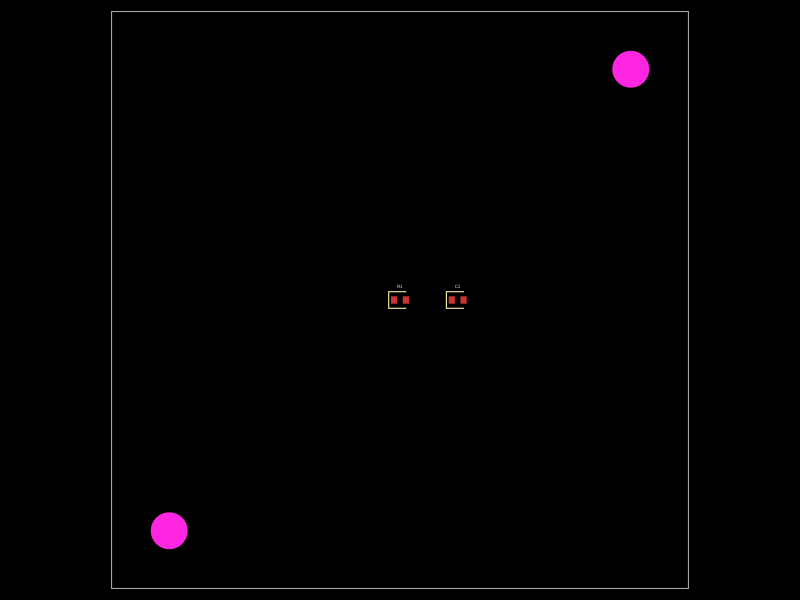 More from this authortechmannih/duplicate-NPTHA 50mm x 50mm PCB layout featuring two mounting holes, a 10kΩ resistor, and a 100nF capacitor positioned at specific coordinates.
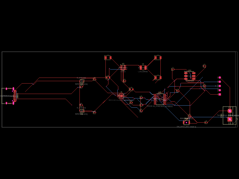 Similar packageaura/diy-power-delivery-triggerThis hardware design implements a USB Type-C port with supporting power management and signal conditioning components, including a USB-C connector, a FUSB302 USB-C port controller, ESD protection diodes, a buck converter for 3.3V power regulation, an STM32 microcontroller for control and processing, an RGB LED indicator, push button, terminal block connections, and associated filtering and support components.
 Discover something new0hmX/dual-usb-peltier-assembly