techmannih/museview
A 50×35 mm USB‑C 5 V camera board combining an ESP32‑S3 module, M0031 parallel camera connector, buck/LDO power rails, USB/ESD protection, controls, status LED, and passives.
- Version
- 0.1.18
- License
- unset
- Stars
- 1
docs/assembly.md
# Assembly

V1.1 is 50 × 35 mm, with USB left, camera connector right and ASK / RESET / BOOT in the south-edge row. All 49 fitted components are on the top side. Bottom assembly is prohibited and checked for every fitted component and SMT pad. Probe pads are bare copper features and must not enter the assembly BOM. BOM and placement CSVs are generated from the final circuit JSON, with exact JLC numbers. Quantities must be regenerated after circuit changes. Copper, drill and JLC centroid coordinates share the board-center origin; negative coordinates are intentional. Do not offset the CPL independently of the Gerbers. Rotation is the tscircuit footprint rotation, so check every polarized part in the JLC placement preview.

- U1: ESP32-S3-WROOM-1-N16R8, not MINI/1U or another memory variant. PCB antenna points toward the north edge. Do not place copper, metal fasteners, battery or enclosure metal in the marked RF keepout. Exposed ground lands need the specified solder paste and solder-mask-covered ground island.
- J1: TYPE-C-31-M-12, facing west. Receptacle mouth intentionally overhangs the board. Verify plated mounting slots and locating holes in the fabrication preview. The shell tabs enter plated slots from the top; their underside annuli are not bottom-mounted components. Request top-side processing for these tabs. The release exporter deliberately leaves B_Paste empty (the pinned generic exporter otherwise adds shell-tab paste on both sides); copper, mask and drills are preserved.
- J2: AFC01-S24FCA-00, 24 contacts at 0.5 mm pitch, bottom contact, 0.30 mm nominal flex. The connector opens toward the east/right board edge; pad 1 is at the south/bottom end of the contact row. “Bottom contact” describes the flex mating contacts, not a bottom-side PCB assembly. Contacts on the mating flex face the PCB; verify the physical M0031 tail's pin 1 and insertion geometry before energizing. Do not force or hot-plug the latch. See [camera mating review](camera-mating.md) for the manufacturer evidence and remaining exact-flex qualification hold.
- D1: SMF5.0A is unidirectional. Cathode is the west/negative-X pad and connects to protected 5 V; anode is ground. Native diode pin aliases are used; physical footprint pad polarity is explicitly preserved.
- LED1: imported KT-0603R polarity; inspect the anode from GPIO17 through R13 and cathode to GND.
- U3/U4/U5: compare pin-1 and package rotations with manufacturer drawings, not only rendered bodies. The 3D asset is a visualization and is not a substitute for a land-pattern drawing. The current angles and actual board pin/polarity landmarks for all critical parts are recorded in [placement-review.md](placement-review.md); JLC preview approval remains pending.
- R6/R7: 432 kΩ and 100 kΩ, **0.1%**, mandatory. R8: 25.5 kΩ, 1%, C22920; R9: 40.2 kΩ, 1%, C2933218. The previous 20.5 kΩ R8 must not be fitted.

All signal and power vias use 0.30 mm plated through drills and 0.60 mm pads across the four-layer stack. No blind or buried vias are specified. See `routing.md` for the decision to retain the active ground and supply planes.

Four corner holes are 2.7 mm nonplated, intended for M2.5 hardware. Use nylon fasteners/standoffs, especially the northeast hole inside the antenna exclusion; no metal screw or enclosure insert is permitted in that RF region. Check screw-head/enclosure clearances. The external camera needs mechanical support; its outline is an assembly note outside the PCB, not fabricated board area.

Imports were downloaded using `tsci import C<number> --jlcpcb --download --use-exact-footprint`. Primitive selection, pin attributes and connectivity aliases were reviewed after import. Standard passives use native tscircuit footprints with explicit supplier identities. R8 uses the native 0603 footprint with the verified C22920 identity; the older 0402 25.5 kΩ candidate is not used.

External items (not JLC assembly): Arducam M0031, rated 5 V USB supply/cable, M2.5 hardware/enclosure. No alternate camera module is approved without rechecking pinout, flex orientation, rail ranges and GPIO timing.
Related Packages
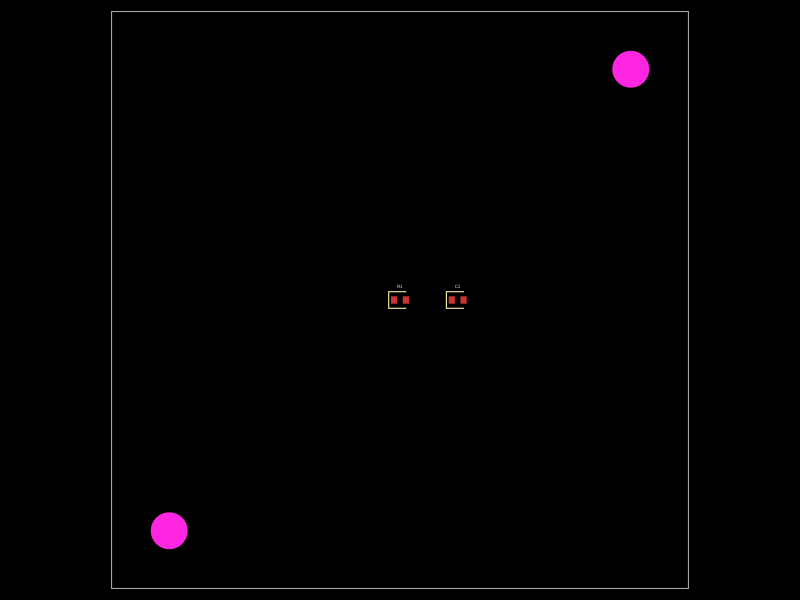 More from this authortechmannih/duplicate-NPTHA 50mm x 50mm PCB layout featuring two mounting holes, a 10kΩ resistor, and a 100nF capacitor positioned at specific coordinates.
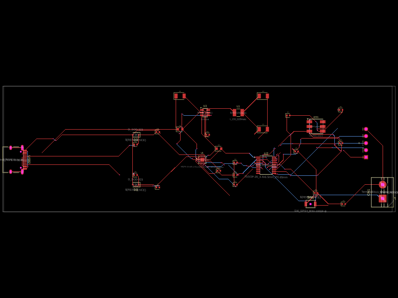 Similar packageaura/diy-power-delivery-triggerThis hardware design implements a USB Type-C port with supporting power management and signal conditioning components, including a USB-C connector, a FUSB302 USB-C port controller, ESD protection diodes, a buck converter for 3.3V power regulation, an STM32 microcontroller for control and processing, an RGB LED indicator, push button, terminal block connections, and associated filtering and support components.
 Discover something new0hmX/dual-usb-peltier-assembly