techmannih/museview
A 50×35 mm USB‑C 5 V camera board combining an ESP32‑S3 module, M0031 parallel camera connector, buck/LDO power rails, USB/ESD protection, controls, status LED, and passives.
- Version
- 0.1.18
- License
- unset
- Stars
- 1
README.md
# MuseView V1
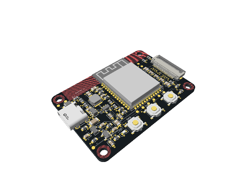
MuseView V1 is a compact Wi-Fi camera controller powered by standard **5 V USB-C**. It connects an **Arducam M0031 OV2640 camera** to an **ESP32-S3-WROOM-1-N16R8**, with dedicated camera power supplies, USB programming, an ASK/CAPTURE button and a status LED on a 50 × 35 mm board.
## Overview
MuseView brings the camera interface, power regulation and controls onto one board. The ESP32 module provides Wi-Fi, 16 MB flash for firmware and 8 MB PSRAM for camera buffers. The external M0031 camera connects through the 24-pin FPC connector on the right edge; the USB-C connector on the left supplies power and provides a programming/debug connection. All PCB assembly components are on the top side.
The included ESP-IDF firmware provides a local photo-capture page. A phone or computer joins the board's Wi-Fi network and opens the page in a browser. Photos can be taken from that page or with the physical ASK button, making the board a starting point for embedded camera projects and image-capture applications.
## How it works
1. **Power the board.** USB-C supplies 5 V through the input protection circuit. The regulators generate the shared 3.192 V MCU/camera I/O supply, 2.8 V camera analog supply and 1.296 V camera core supply.
2. **Initialize the camera.** After startup, the ESP32 releases the camera's power-down/reset controls, configures the OV2640 and receives image data over its 8-bit DVP interface. The supplied firmware captures JPEG images at SVGA resolution using PSRAM-backed camera buffers.
3. **Connect over Wi-Fi.** With the firmware flashed, join `MuseView-XXXXXX` using the configured Wi-Fi password, then open `http://192.168.4.1/`. The ESP32 serves the capture page directly to the connected device.
4. **Take a photo.** Click **Capture** in the browser or press **ASK/CAPTURE** on the board. The LED lights during capture. **Last ASK capture** displays the most recently cached image; the latest JPEG is kept in RAM and replaced by the next capture. Images stay on the local connection and are not stored permanently.
5. **Program or recover.** USB supports firmware flashing and serial debugging. RESET restarts the board; holding BOOT while pressing RESET enters the ESP32 ROM download mode.
See the [firmware setup guide](https://github.com/techmannih/museview-v1/blob/main/firmware/README.md) for Wi-Fi configuration, flashing and the browser interface.
## Use
```sh
bun install --frozen-lockfile
bun run verify
bun run dev
bun run build:preview
bun run build:handoff
bun run export:assembly
bun run snapshot
bun run snapshot:3d
bun run export:release
```
The library/CLI is pinned to tscircuit 0.0.2687. Builds use selected supplier numbers, not automatic part substitution. `hardware-contract.json` is checked against the generated source netlist. `scripts/check-decoupling.mjs` measures actual local copper. The strict `bun run check:schematic-style` gate runs Style Analysis 0.0.39 on all four built sheets and fails on any issue; the native CLI placement command only prints suggestions. Its dependencies are isolated while explicit pins preserve the existing PCB runtime. Placement, routing diagnostics and a separate Gerber copper short check must pass before a release can be considered.
Start the viewer with `bun run dev` (optionally `--port 3020`) after installing the locked dependencies. The launcher requires the local pinned CLI and refuses a missing or mismatched installation. A bare global `tsci dev` can load a different browser renderer and produce a stale-routing error followed by disconnected-port errors; see [viewer troubleshooting](https://github.com/techmannih/museview-v1/blob/main/docs/routing.md#viewer-troubleshooting). The separately published website renderer is supported for its reviewed mounting-keepout representation; it still rejects other stale routing inputs.
## Design
- 50 × 35 mm, 1.6 mm FR4, four copper layers, black solder mask, **all 49 fitted components on top; no bottom assembly**.
- Via minima: **0.30 mm hole / 0.45 mm pad**. Actual through vias: **0.30 mm drill / 0.60 mm pad**, with 0.15 mm annular rings.
- L1 components/signals, L2 ground reference, L3 common MCU/camera I/O power, L4 signals. Antenna keepout on all copper layers.
- USB-C USB 2.0 device: independent 5.1 kΩ CC pull-downs, USBLC6-2SC6, 33 Ω data resistors, 750 mA PTC, SMF5.0A input TVS.
- TLV62569: **3.192 V nominal** shared ESP32/camera I/O, using 432 kΩ/100 kΩ, both **0.1%**.
- XC6206P282MR: camera analog 2.8 V, supplied from protected USB 5 V to avoid marginal dropout headroom.
- SGM2059: camera core **1.296 V nominal**, using 25.5 kΩ/40.2 kΩ, both 1%. Net: **CAM_1V3**, TP7 acceptance **1.24–1.36 V**.
- Native USB ROM recovery, UART0/JTAG pads, BOOT, RESET, ASK GPIO16 and LED GPIO17.
- Camera RESET GPIO18 defaults low and PWDN GPIO8 defaults high. Firmware must actively release them.
These rail choices retain the corrected 1.296 V camera core and avoid a marginal 2.8 V camera-to-3.318 V ESP32 I/O interface. See [electrical decisions](https://github.com/techmannih/museview-v1/blob/main/docs/electrical-review.md) and the [pin contract](https://github.com/techmannih/museview-v1/blob/main/hardware-contract.json).
## Repository
The repository contains the MuseView board entrypoint, local component and CAD imports, a Bun lockfile, automated checks and schematic/PCB/3D snapshots.
```text
index.circuit.tsx board, four schematic sheets, placement and copper
pcb-routes.json reviewed routes, guarded by geometry/net fingerprint
routing/ native geometry and pinned routing-generation inputs
imports/ JLC-imported ICs/connectors/CAD; native passives
scripts/ verification, mutation tests and exports
sourcing/ timestamped JLCSearch evidence and alternatives
__snapshots__/ reviewed schematic, PCB and 3D renders
docs/ assembly, electrical review, bring-up, release checks
firmware/ matching ESP-IDF camera bring-up application
.github/workflows/ automated build/check pipeline
dist/ generated CAD/manufacturing output (ignored)
release/ published, versioned handoff files
```
USB-C is on the left, the camera connector is on the right, the antenna faces the top edge, and ASK / RESET / BOOT sit along the bottom edge. Bottom copper carries routing; all fitted components are on top.
## Assembly boundary
The external Arducam M0031 camera, USB cable and enclosure are not JLCPCB assembly components. JLCSearch quantities are cached catalogue evidence, not reserved stock or a confirmed assembly quotation. Recheck the selected BOM in JLC's assembly portal immediately before ordering. FPC mating, prototype rail/transient measurements, USB signal integrity and camera capture require hardware validation; successful software checks do not establish those results.
Component import/stock provenance and datasheets: [sources](https://github.com/techmannih/museview-v1/blob/main/docs/sources.md). Current validation and open physical checks: [release checks](https://github.com/techmannih/museview-v1/blob/main/docs/release-checks.md).
View the four schematic sheets: [USB](https://github.com/techmannih/museview-v1/blob/main/release/schematic-usb.svg), [power](https://github.com/techmannih/museview-v1/blob/main/release/schematic-power.svg), [MCU](https://github.com/techmannih/museview-v1/blob/main/release/schematic-mcu.svg), [camera](https://github.com/techmannih/museview-v1/blob/main/release/schematic-camera.svg). Board views: [top](https://github.com/techmannih/museview-v1/blob/main/release/pcb-top.svg), [bottom](https://github.com/techmannih/museview-v1/blob/main/release/pcb-bottom.svg). Editable manufacturing/CAD exports: [Gerbers](https://github.com/techmannih/museview-v1/blob/main/release/museview-v1-gerbers.zip), [KiCad](https://github.com/techmannih/museview-v1/blob/main/release/museview-v1-kicad.zip), [STEP ZIP](https://github.com/techmannih/museview-v1/blob/main/release/museview-v1-step.zip), [GLB](https://github.com/techmannih/museview-v1/blob/main/release/museview-v1.glb). See [routing workflow](https://github.com/techmannih/museview-v1/blob/main/docs/routing.md) before changing placement or nets.
Related Packages
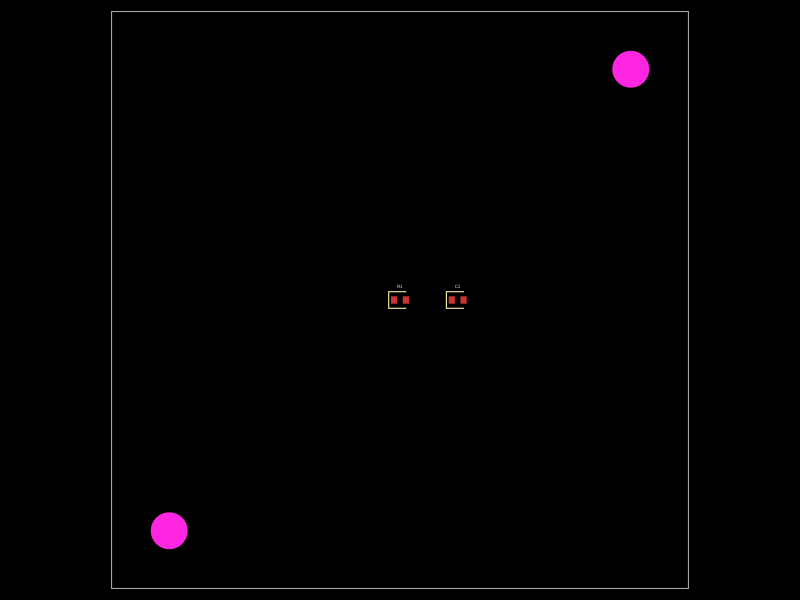 More from this authortechmannih/duplicate-NPTHA 50mm x 50mm PCB layout featuring two mounting holes, a 10kΩ resistor, and a 100nF capacitor positioned at specific coordinates.
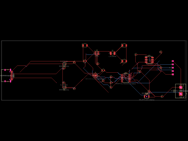 Similar packageaura/diy-power-delivery-triggerThis hardware design implements a USB Type-C port with supporting power management and signal conditioning components, including a USB-C connector, a FUSB302 USB-C port controller, ESD protection diodes, a buck converter for 3.3V power regulation, an STM32 microcontroller for control and processing, an RGB LED indicator, push button, terminal block connections, and associated filtering and support components.
 Discover something new0hmX/dual-usb-peltier-assembly