shibosoftwaredev/f1c100s-linux-nema17-stepper-controller
Compact four-layer NEMA 17 carrier PCB combining an F1C100S Linux SoC, USB-C PD power and buck regulation, W5500 10/100 Ethernet, STM32 safety/motion control, and DRV8825 stepper-driver hardware with protection, sensing, connectors, and dual-sided SMT assembly.
- Version
- 0.4.15
- License
- unset
- Stars
- 0
motion-controller.tsx
import { Fragment } from "react"
import { STM32G030F6P6 } from "./imports/STM32G030F6P6"
import { BSS84_7_F } from "./imports/BSS84_7_F"

const wire = (name: string, from: string, to: string, thickness = 0.15) =>
  <trace name={name} from={from} to={to} thickness={thickness} />

const resistor = (name: string, value: string, lcsc: string, x: number, y: number,
  layer: "top" | "bottom" = "bottom", schX = x, schY = y) =>
  <resistor name={name} layer={layer} resistance={value} footprint="0402"
    supplierPartNumbers={{jlcpcb:[lcsc]}} pcbX={x} pcbY={y} schX={schX} schY={schY}
    schRotation={name === "R_MOTION_ENABLE_PD" ? -90 : undefined} />

const smdTestPoint = <footprint>
  <smtpad portHints={["pin1"]} pcbX={0} pcbY={0} width="1.5mm" height="1.5mm" shape="rect" />
</footprint>

/**
 * The STM32G0 owns STEP/DIR, driver enable and temperature polling. Linux sends
 * framed UART commands and a heartbeat, but never generates step pulses. The
 * MCU firmware must enable its independent watchdog and enforce a command
 * timeout. Reset/BOOT0 are driven by Linux so field firmware updates can use the
 * STM32 ROM UART bootloader. Both reset and loss of PD force the bridge asleep.
 */
export function MotionController() {
  return <group name="MOTION" pcbX={0} pcbY={0} schX={-30} schY={25.5} schSheetName="motion">
    <STM32G030F6P6 name="U_MOTION" layer="bottom" pcbX={-1.75} pcbY={2.0} pcbRotation={180}
      schX={18} schY={-22}
      noConnect={["PB7_PB8","PB9_PC14_OSC32_IN","PC15_OSC32_OUT","PA1","PB0_PB1_PB2_PA8","PB3_PB4_PB5_PB6"]} />
    <capacitor name="C_MOTION" layer="bottom" capacitance="100nF" maxVoltageRating={16} footprint="0402"
      maxDecouplingTraceLength={26}
      supplierPartNumbers={{jlcpcb:["C1525"]}} pcbX={-2.4} pcbY={7.1} pcbRotation={270}
      schX={12} schY={-20} schRotation={-90} />
    <capacitor name="C_MOTION_BULK" layer="bottom" capacitance="4.7uF" maxVoltageRating={16} footprint="0603"
      manufacturerPartNumber="CL10A475KO8NNNC" supplierPartNumbers={{jlcpcb:["C19666"]}}
      maxDecouplingTraceLength={25}
      pcbX={-17.0} pcbY={-16.3} schX={12} schY={-23} schRotation={-90} />
    {wire("MOTION_GND", ".U_MOTION > .pin5", "net.BOARD_GND", 0.3)}
    <trace name="MOTION_BYPASS_VDD" from=".C_MOTION > .pin1" to=".U_MOTION > .pin4"
      thickness={0.12} maxLength={4} pcbStraightLine />
    <trace name="MOTION_BYPASS_GND" from=".C_MOTION > .pin2" to="net.BOARD_GND"
      thickness={0.12} maxLength={4} pcbStraightLine />
    {wire("MOTION_BULK_VDD", ".C_MOTION_BULK > .pin1", ".C_MOTION > .pin1", 0.3)}
    {wire("MOTION_BULK_GND", ".C_MOTION_BULK > .pin2", "net.BOARD_GND", 0.3)}

    {/* Linux-to-MCU UART and the two programming controls. */}
    {wire("MOTION_UART_TX", ".U_MOTION > .pin9", "net.MOTION_TX")}
    {wire("MOTION_UART_RX", ".U_MOTION > .pin10", "net.MOTION_RX")}
    {wire("MOTION_NRST", ".U_MOTION > .NRST", "net.MOTION_NRST")}
    {wire("MOTION_BOOT", ".U_MOTION > .pin19", "net.MOTION_BOOT")}
    <resistor name="R_MOTION_RESET" layer="bottom" resistance="10k" footprint="0402"
      supplierPartNumbers={{jlcpcb:["C25744"]}} pcbX={-18.5} pcbY={-9.0}
      schX={22} schY={-15.8} schRotation={90} />
    <resistor name="R_MOTION_BOOT" layer="bottom" resistance="100k" footprint="0402"
      supplierPartNumbers={{jlcpcb:["C25741"]}} pcbX={15.72} pcbY={-15.5} pcbRotation={90}
      schX={24} schY={-22} schRotation={-90} />
    <capacitor name="C_MOTION_RESET" layer="bottom" capacitance="100nF" maxVoltageRating={16} footprint="0402"
      supplierPartNumbers={{jlcpcb:["C1525"]}} pcbX={24} pcbY={-25}
      schX={24} schY={-25} schRotation={-90} />
    {wire("MOTION_RESET_PULLUP", ".R_MOTION_RESET > .pin1", "net.MOTION_NRST")}
    {wire("MOTION_RESET_PULLUP_VDD", ".R_MOTION_RESET > .pin2", ".C_MOTION > .pin1")}
    {wire("MOTION_RESET_CAP", ".C_MOTION_RESET > .pin1", "net.MOTION_NRST")}
    {wire("MOTION_RESET_CAP_GND", ".C_MOTION_RESET > .pin2", "net.BOARD_GND")}
    {/* PA14 is both BOOT0 and SWCLK on this STM32G0 package. Put the Linux
        control, pulldown, MCU pin and factory pad on one explicit net. */}
    {wire("MOTION_BOOT_PULLDOWN", ".R_MOTION_BOOT > .pin1", "net.MOTION_BOOT")}
    {wire("MOTION_BOOT_PULLDOWN_GND", ".R_MOTION_BOOT > .pin2", "net.BOARD_GND")}

    {/* Timer output and safety inputs own the motor stage. */}
    {wire("MOTION_STEP", ".U_MOTION > .pin13", "net.MOTOR_STEP")}
    {wire("MOTION_DIR", ".U_MOTION > .pin14", "net.MOTOR_DIR")}
    {wire("MOTION_ENABLE_RAW", ".U_MOTION > .pin11", "net.MOTOR_ENABLE_RAW")}
    {wire("MOTION_FAULT", ".U_MOTION > .pin12", "net.MOTOR_FAULT")}
    {wire("MOTION_TEMP_ALERT", ".U_MOTION > .pin7", "net.MOTION_TEMP_ALERT")}
    {wire("MOTION_I2C_SCL", ".U_MOTION > .pin16", "net.MOTION_I2C_SCL")}
    {wire("MOTION_I2C_SDA", ".U_MOTION > .pin17", "net.MOTION_I2C_SDA")}

    {/* PG-low turns on the P-channel pass gate. Any reset leaves both sides low. */}
    <BSS84_7_F name="Q_PD_ENABLE" layer="top" pcbX={10.7} pcbY={-13.1388} pcbRotation={90}
      schX={29} schY={-18} />
    {resistor("R_MOTION_ENABLE_PD", "100k", "C25741", -9, -7.2, "bottom", 29, -21)}
    {wire("PD_GATE_SOURCE", ".Q_PD_ENABLE > .S", "net.MOTOR_ENABLE_RAW")}
    {wire("PD_GATE_DRAIN", ".Q_PD_ENABLE > .D", "net.MOTOR_ENABLE")}
    {wire("MOTION_ENABLE_RAW_PD", ".R_MOTION_ENABLE_PD > .pin1", "net.MOTOR_ENABLE_RAW")}
    {wire("MOTION_ENABLE_RAW_PD_GND", ".R_MOTION_ENABLE_PD > .pin2", "net.BOARD_GND")}

    {/* Factory/recovery access only; these are compact SMD pads, not expansion headers. */}
    {[
      ["SWDIO", ".U_MOTION > .pin18", 11],
      ["SWCLK", "net.MOTION_BOOT", 14],
      ["NRST", "net.MOTION_NRST", 17],
      ["GND", "net.BOARD_GND", 20],
    ].map(([label, target, x]) => <Fragment key={label as string}><group pcbX={0} pcbY={0} schX={0} schY={0}>
      <testpoint name={`TP_MOTION_${label}`} layer="bottom" footprint={smdTestPoint}
        pcbX={x as number} pcbY={-34} schX={x as number} schY={-34} />
      {wire(`MOTION_TP_${label}`, `.TP_MOTION_${label} > .pin1`, target as string)}
      <silkscreentext text={label as string} pcbX={x as number} pcbY={-35.5} fontSize={0.55} />
    </group></Fragment>)}

    <silkscreentext text="STM32 MOTION / WATCHDOG" pcbX={19} pcbY={-28} fontSize={0.65} />
  </group>
}
Related Packages
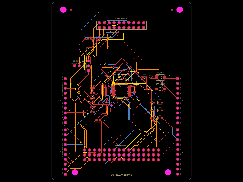 More from this authorShiboSoftwareDev/captivate-fr2676This circuit implements an MSP430FR2676 microcontroller-based development module with integrated power regulation, user interface components, programming interfaces, and sensor/boosterpack headers for embedded system prototyping.
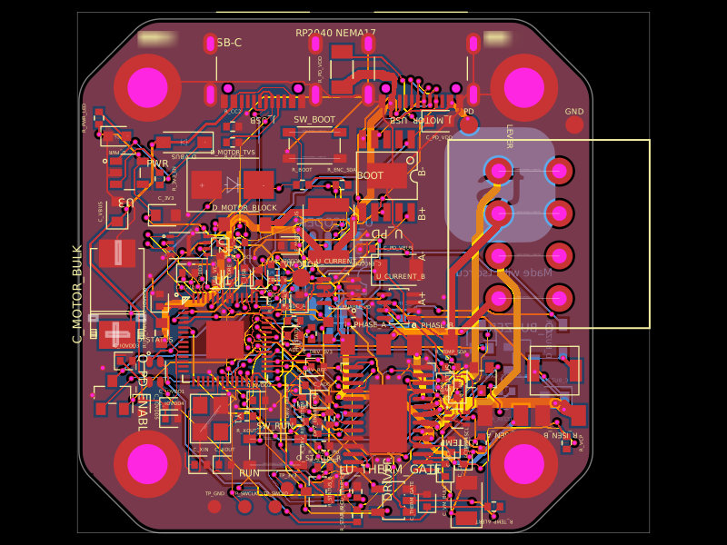 Similar packageastra/nema17-stepper-motor-controller-spring-clamp-rp2040A 4-layer RP2040 controller board that negotiates USB‑C PD motor power and drives a NEMA17 stepper via a DRV8825, with current sensing, thermal shutdown, RGB status LED, buzzer alarm, optional AS5600 encoder, protection/filtering, and test points.
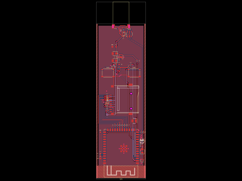 Discover something newpixalynx/esp32-usb-duckyA compact ESP32‑S3 USB‑C stick with native USB HID, 4‑bit microSD storage, 3.3V LDO power regulation, ESD protection, boot/reset controls, addressable RGB status LED, decoupling, and test pads.