seveibar/nema17-rp2040-stepper-controller
A tscircuit package created by seveibar.
- Version
- 0.3.1
- License
- unset
- Stars
- 0
mechanical/README.md
# NEMA 17 rear-mounted controller

Revision D uses a 42 × 42 mm square board, with four 3.3 mm mounting holes at (±15.5, ±15.5) mm. The hole pitch is 31 mm in both axes. Grounded mounting rings are 5.6 mm in diameter; the placement reserves 6.5 mm screw-head clearance circles.

All populated components occupy the top side. Use insulated standoffs with enough clearance for through-hole solder joints and the motor rear shaft/bearing boss. The AS5600 at the board origin and its supporting passives are unpopulated in this assembly. The motor housing must not touch the PCB or exposed conductors. Choose screw length from the actual motor and spacer stack.

USB connector bodies and courtyards fit within the 42 mm outline; plugged-in cables extend outwards. The motor output uses a four-pin JST PH connector, 2 mm pitch. Verify the actual motor fasteners and cable pinout before assembly.

`mounting-template.svg` shows the current board at 1:1 scale. Print at 100% and verify its 31 mm hole pitch. `nema17-outline.json` retains the earlier rounded reference perimeter for provenance; it is not the active revision D outline. The active outline is defined in `index.circuit.tsx`.

The earlier reference perimeter came from [PD-Stepper V1.1](https://github.com/joshr120/PD-Stepper/tree/3c40073a0ec51653f6ea48c70f365bd7f9f3bdcc/PCB); its GPL-3.0 license is retained as `PD-Stepper-LICENSE`. Its cover and heatspreader are not interchangeable with this layout.

## Optional encoder population

The encoder is DNP in revision D; the following applies only to a future assembly that populates it. The board origin must align with the motor shaft. Fit a diametrically magnetized on-axis magnet to an accessible rear shaft, facing the AS5600. The exact magnet, holder and axial gap depend on the motor, which has not been specified. Start from the sensor manufacturer’s magnet guidance and adjust until sensor readings confirm a valid magnetic field through a full revolution. Ensure the magnet cannot strike the chip and keep the buzzer opening clear. This is single-turn position sensing; there is no shaft pass-through hole at the board centre.
Related Packages
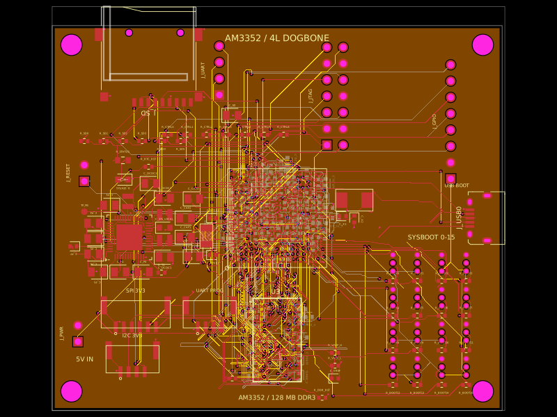 More from this authorseveibar/am3352-dev-board-4layer-dogboneDefines PCB footprints and pin mappings for a TI AM3352ZCZ100 processor, JST GH connectors, and assembly-part lookup helpers for capacitors, resistors, and headers.
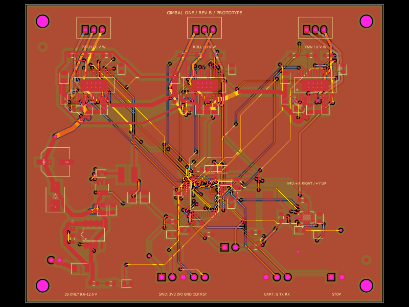 Discover something newmohan-bee/gimbal-one-budget-pcbA 4-layer STM32-based gimbal controller PCB with an onboard LSM6DS3TR-C IMU, three DRV8313 3-phase motor drivers, protected 3S battery input, 3.3 V buck regulation, and SWD/UART control interfaces.