seveibar/led-water-accelerometer
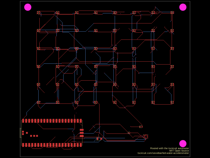
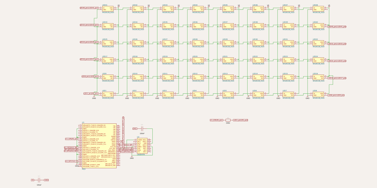
This is an LED matrix with an accelerometer and a PICO. When you tilt the PCB, the LEDs dim and change color to simulate water flowing.
- Version
- 1.0.18
- License
- unset
- Stars
- 7
index.tsx
PCB
Schematic
import { LIS3DHTR as IMU } from "./imports/LIS3DHTR"
import { WS2812B_2020 as LedWithIc } from "@tsci/seveibar.WS2812B_2020"
import { PICO } from "@tsci/seveibar.PICO"
import { grid } from "@tscircuit/math-utils"
import { sel } from "@tscircuit/core"

/**
 * Updated board description that fixes the power‑/ground‑/data‑line issues
 * highlighted in the design review:
 *   • Single common GND net
 *   • Sensor powered from Pico 3V3_OUT (and VDDIO tied as well)
 *   • Series 330 Ω resistor on the LED data line
 *   • Bulk and local decoupling capacitors for the LED string
 */
export default () => (
  <board width={142} height={130}>
    {/* ───────────────────────────────────────── LED MATRIX ───────────────────────────────────────── */}
    {grid({
      cols: 8,
      rows: 6,
      xSpacing: 32,
      ySpacing: 30,
      offsetX: 0,
      offsetY: 36,
    }).map(({ center, index, row, col }) => {
      /* zero‑based index → user‑facing 1‑based name */
      const ledNum = index + 1
      const ledName = `LED${ledNum}`
      const prevLedName = ledNum > 1 ? `LED${ledNum - 1}` : null

      return (
        <group key={ledName} pcbX={center.x / 2} pcbY={center.y / 2} schX={col * 3.5 - 24} schY={row * 2}>
          {/* ➊ LED itself */}
          <LedWithIc
            name={ledName}
          />

          {/* ➌ LED power / ground stitching */}
          <trace from={`.${ledName} .GND`} to="net.GND" />
          <trace from={`.${ledName} .VDD`} to="net.V5" />

          {/* ➍ Data daisy‑chain */}
          {prevLedName && (
            <trace from={`.${prevLedName} .DO`} to={`.${ledName} .DI`} />
          )}
        </group>
      )
    })}

    {/* ───────────────────────────────────────── CORE PARTS ───────────────────────────────────────── */}
    <PICO
      name="U1"
      pcbY={-45}
      pcbX={-44}
      schX={-25}
      schY={-6}
      schWidth={4}
      showPinAliases
    />
    <IMU name="U2" schX={-20} schY={-6} pcbY={-48} pcbX={34} />

    {/* ───────────────────────────────────────── BULK DECOUPLING ─────────────────────────────────── */}
    <capacitor
      name="C2"
      footprint="1206"
      capacitance="100uF"
      pcbX={-5}
      pcbY={-50}
      schX={-32}
      schY={-10}
    />
    <trace from={sel.C2.pin1} to="net.V5" />
    <trace from={sel.C2.pin2} to="net.GND" />

    {/* ───────────────────────────────────────── IMU DECOUPLING ─────────────────────────────────── */}
    <capacitor
      name="C1"
      footprint="0402"
      capacitance="100nF"
      schX={-20}
      schY={-4}
      schRotation={180}
      pcbX={20}
      pcbY={-45}
    />
    <trace from={sel.C1.pin1} to={sel.U1["3V3_OUT"]} />
    <trace from={sel.C1.pin2} to="net.GND" />

    {/* ───────────────────────────────────────── DATA‑LINE RESISTOR ──────────────────────────────── */}
    <resistor
      name="R1"
      footprint="0603"
      resistance="330"
      schX={-10}
      schY={-3}
      pcbX={30}
      pcbY={-40}
    />
    <trace from={sel.U1.GP6} to={sel.R1.pin1} />
    <trace from={sel.R1.pin2} to={sel.LED1.DI} />

    {/* ───────────────────────────────────────── POWER (3V3) ─────────────────────────────────────── */}
    {/* Sensor core & I/O rails on Pico's regulated 3V3 */}
    <trace from={sel.U1["3V3_OUT"]} to={sel.U2.VDD} />
    <trace from={sel.U1["3V3_OUT"]} to={sel.U2.VDDIO} />

    {/* ───────────────────────────────────────── POWER LEDS ─────────────────────────────────────── */}
    <trace from={sel.U1["VBUS"]} to={"net.V5"} />

    {/* ───────────────────────────────────────── MOUTING HOLES ─────────────────────────────────────── */}
    <hole pcbX={-65} pcbY={60} radius={3} />
    <hole pcbX={65} pcbY={60} radius={3} />
    <hole pcbX={65} pcbY={-54} radius={3} />

    {/* ───────────────────────────────────────── GROUNDS ─────────────────────────────────────────── */}
    {/* Stitch several of the Pico & IMU grounds into the common pour */}
    {[
      sel.U1(PICO).GND1,
      sel.U1(PICO).GND2,
      sel.U1(PICO).GND3,
      sel.U1(PICO).GND4,
      sel.U1(PICO).GND5,
      sel.U2(IMU).GND1,
      sel.U2(IMU).GND2,
    ].map((pin, i) => (
      <trace key={`g${i}`} from={pin} to="net.GND" />
    ))}

    {/* ───────────────────────────────────────── SPI CONNECTIONS ─────────────────────────────────── */}
    <trace from={sel.U1.GP10} to={sel.U2.SPC} />
    <trace from={sel.U1.GP11} to={sel.U2.SDI} />
    <trace from={sel.U1.GP12} to={sel.U2.SDO} />
    <trace from={sel.U1.GP17} to={sel.U2.CS} />
    <group pcbY={-59}>
      <silkscreentext
        text="Routed with the tscircuit autorouter"
        pcbX={70}
        pcbY={0}
        fontSize={2}
        anchorAlignment="bottom_right"
      />
      <silkscreentext
        text="MIT Open Source"
        pcbX={70}
        pcbY={-2}
        fontSize={2}
        anchorAlignment="bottom_right"
      />
      <silkscreentext
        text="tscircuit.com/seveibar/led-water-accelerometer"
        pcbX={70}
        pcbY={-4}
        fontSize={2}
        anchorAlignment="bottom_right"
      />
    </group>
  </board>
)