seveibar/f1c100s-linux-dev-board
A 4-layer F1C100S Linux development carrier board with USB‑C power/data, multi-rail LDOs, SPI NOR flash, reset/boot interfaces, I²C/SPI/UART headers, ESD protection, and a buffered 5‑V clocked RGB LED.
- Version
- 1.9.2
- License
- unset
- Stars
- 1
firmware/carrier.dtsi
/* Include after suniv-f1c100s.dtsi in your board DTS. This is a hardware
 * integration fragment, not a complete bootable board description. */
#include <dt-bindings/gpio/gpio.h>

/ {
    aliases { serial0 = &uart0; i2c0 = &i2c0; spi0 = &spi0; spi1 = &spi1; };
    chosen { stdout-path = "serial0:115200n8"; };
    /* SK9822-A uses PE2 data and PE3 clock through a 5 V AHCT buffer.
     * Keep these as GPIOs for firmware/rgb-demo.py; no gpio-leds binding. */
};
&pio {
    carrier_i2c0: i2c0-pe-pins { pins = "PE11", "PE12"; function = "i2c0"; };
    carrier_spi1: spi1-pe-pins { pins = "PE7", "PE8", "PE9", "PE10"; function = "spi1"; };
};
&uart0 { pinctrl-names = "default"; pinctrl-0 = <&uart0_pe_pins>; status = "okay"; };
&i2c0 {
    pinctrl-names = "default"; pinctrl-0 = <&carrier_i2c0>;
    clock-frequency = <100000>; status = "okay";
    /* Add the actual attached I2C peripheral here. */
};
&spi0 {
    pinctrl-names = "default"; pinctrl-0 = <&spi0_pc_pins>; status = "okay";
    flash@0 {
        compatible = "winbond,w25q128", "jedec,spi-nor";
        reg = <0>; spi-max-frequency = <24000000>;
        /* Partition layout must match your SPL/U-Boot/Linux image. */
    };
};
&spi1 {
    pinctrl-names = "default"; pinctrl-0 = <&carrier_spi1>; status = "okay";
    /* Add your real SPI peripheral at CS0; start at <= 1 MHz over the cable.
     * Do not use a fictitious compatible string just to bind spidev. */
};
&usb_otg { dr_mode = "peripheral"; status = "okay"; };
&usbphy { status = "okay"; };
Related Packages
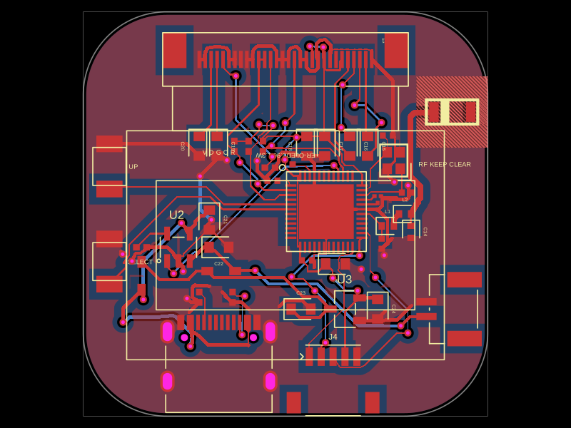 More from this authorseveibar/nrf-smart-watchThis code defines a detailed 3D PCB layout with schematic components, connectors, passive components, and RF antenna elements for a compact nRF52810-based smartwatch, including precise placement, copper pours, keepouts, and annotations.
 Similar packageShiboSoftwareDev/mspm0g3507-usb-c-dev-boardThe circuit assembles a USB-C port with integrated ESD protection, power regulation, UART interface, and microcontroller (MSPM0G3507) with supporting components for USB data lines, CC termination, I2C, SPI, reset circuitry, and indicator LEDs.
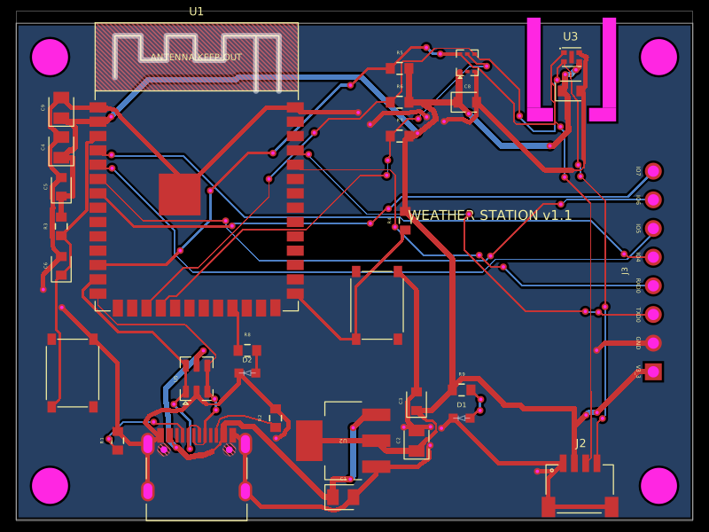 Discover something newolivergrabinski/tscircuit-weatherA 60×44 mm ESP32-S3 Wi‑Fi/BLE weather-station PCB with USB‑C power, 3.3 V regulation and ESD protection, temperature/humidity and UV/light sensors, status LEDs, buttons, Qwiic I²C expansion, debug GPIO header, and a printable enclosure.