sang-it/led-connectivity-tester
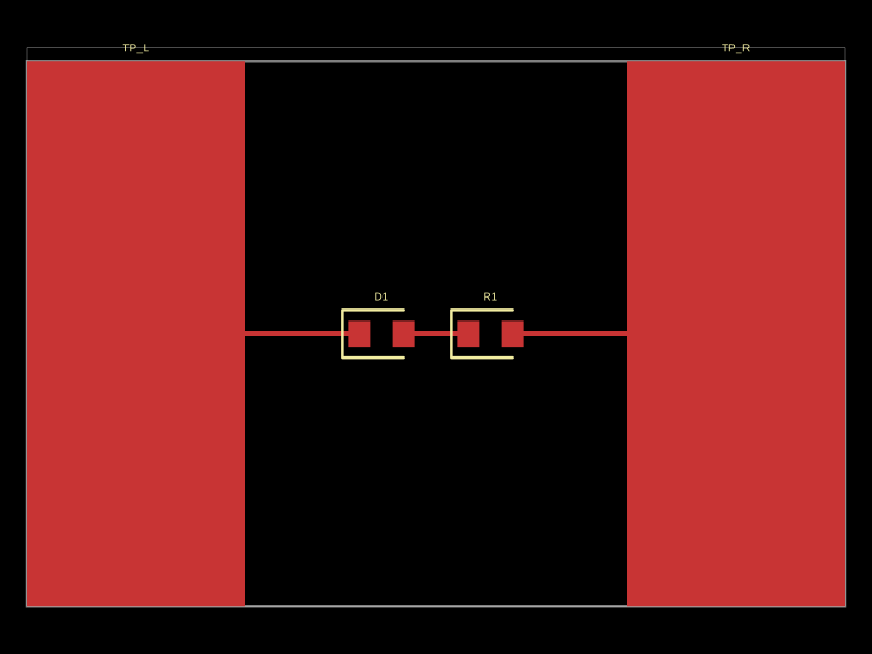
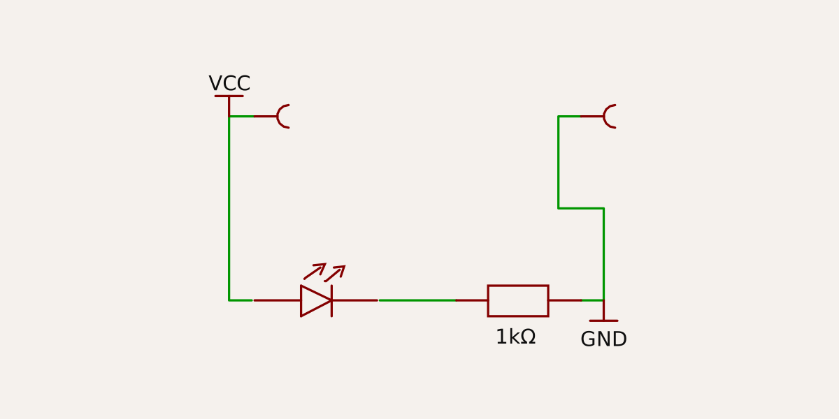
This code defines a PCB with a power supply line, an LED (D1), a resistor (R1), and two external test points connected to VCC and GND.
- Version
- 1.0.0
- License
- unset
- Stars
- 0
index.circuit.tsx
PCB
Schematic
const BOARD_W = 30;
const BOARD_H = 20;
const PAD_W = 8;

export default () => (
  <board width={BOARD_W} height={BOARD_H}>
    <net name="VCC" isPowerNet />
    <net name="GND" isGroundNet />

    <led name="D1" footprint="0603" pcbX={-2} pcbY={0} />
    <resistor name="R1" resistance="1k" footprint="0603" pcbX={2} pcbY={0} />

    <trace from=".D1 > .pin2" to=".R1 > .pin1" />
    <trace from=".D1 > .pin1" to="net.VCC" />
    <trace from=".R1 > .pin2" to="net.GND" />

    <testpoint
      name="TP_L"
      footprintVariant="pad"
      padShape="rect"
      width={PAD_W}
      height={BOARD_H}
      pcbX={-BOARD_W / 2 + PAD_W / 2}
      pcbY={0}
    />
    <trace from=".TP_L > .pin1" to="net.VCC" />

    <testpoint
      name="TP_R"
      footprintVariant="pad"
      padShape="rect"
      width={PAD_W}
      height={BOARD_H}
      pcbX={BOARD_W / 2 - PAD_W / 2}
      pcbY={0}
    />
    <trace from=".TP_R > .pin1" to="net.GND" />
  </board>
);