rushabhcodes/desk-fidget-counter
A desk knob assembly combining a circuit board with PETG-printed mechanical parts and vendor CAD-modeled hardware.
- Version
- 5.6.1
- License
- MIT
- Stars
- 0
validation/BRINGUP.md
# E4 PCB / E5 enclosure prototype bring-up

**All physical checks below are pending.** Record board/firmware tag, instruments, measurements and photographs. Software, CAD, routing and image checks do not replace a first assembled prototype.

## Power and USB

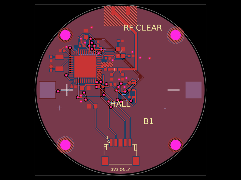
- [ ] Inspect bare board and soldering against Gerbers, pin-1 drawing and BOM. Confirm VBUS / V3V3 / PERIPH_3V3 / GND isolation. U4 is the SC70 load switch, not a charger.
- [ ] Use a current-limited USB test setup. Confirm always-on 3.3V, low PB2/peripheral rail before configuration, no heating, and stable output under load.
- [ ] Verify VBUS inrush, steady operation below the declared 100mA, load-switch ramp, display/IR current and both USB-C orientations with the specified cable.
- [ ] Confirm USB HID+CDC enumeration on macOS, Windows and Linux. Test cold boot, warm reset, rapid hotplug and laptop sleep/wake.
- [ ] Suspend USB, disconnect the SWD probe, and measure total VBUS current against the applicable USB suspend limit. Confirm LCD/IR power off, no high LCD inputs/back-powering, Stop-mode entry and EXTI18 wake. Scope HSI48/USB resume timing and repeated suspend/reset cycles; no compliance is claimed before measurement.
- [ ] Turn the ring during suspension: no counts/scrolling should be guessed or replayed after resume. Existing committed count must survive.

## Programming, persistence and screen

- [ ] Meter J4's VTref/SWDIO/SWCLK/NRST/GND/BOOT0 mapping before connecting the probe. Program/verify firmware 5.0.0 over SWD. Exercise ROM recovery separately.
- [ ] Initialize FRAM with RESET CONFIRM. Test power removal during every journal write stage; recover a valid prior/committed record, never a corrupted guessed value. Document the brief possible rollback of an in-flight completed-turn write.
- [ ] Shorten the supplied H1 according to the physical signal-to-signal map in manufacturing/WIRING.md. Verify all eight continuities, no adjacent shorts, correct VCC/GND, retained factory PH latch and termination strength. Verify the actual screen connector revision/position against the supplier STEP.
- [ ] Confirm GC9A01 startup/orientation with tab -X, MADCTL 0xA8, RGB order, backlight, and readability. Test count up to 20 digits and HOLD 3S TO INIT and TIMER ERROR fault states. A write-only SPI transport-success flag cannot detect an unplugged screen.
- [ ] Run the companion on intended OSes. Compare local clock/date, total CPU%, RAM%, battery%/AC to host tools. Test no-battery desktop, companion close/reopen, multiple devices, port already in use and laptop disconnect/reconnect.
- [ ] Stop updates: after five seconds, replace clock/metrics with HOST OFFLINE while scrolling/counting continue on awake USB. Check midnight/date rollover, timezone changes and host clock adjustments.

## Optical counting and controls

- [ ] Verify U2 collector is on PERIPH_3V3, common cathode to GND, separate emitter pulldowns and nominal IR current. Scope both Schmitt inputs and PB4/PB5.
- [ ] Confirm 48 periods/channel and exactly 192 combined edges per full revolution, approximately quadrature phase, and high/low voltage margins.
- [ ] Test 950nm opacity of the printed skirt, slots, axial/radial alignment, dust, sunlight and room lighting. Black visible colour alone is insufficient.
- [ ] Compare 10/100/1000 measured turns both directions. Exercise slow edges, reversals, stopping on transitions and maximum intended speed while display and FRAM run. Measure a reliable speed envelope.
- [ ] Confirm wheel direction and 32 units per turn. Short-press while rotating: switch Scroll / Count-only, counting continues, and no queued wheel motion replays. Confirm Count-only at boot.
- [ ] Test the front button’s three-second hold and intentional CDC reset. Confirm hold progress and COUNT CLEARED, one clear per hold, no mode change on long release, and no action if held at boot/resume. Unknown/corrupt FRAM must require initialization.

## Mechanics and fabrication

- [ ] Print the nominal bearing-fit coupon first with the actual bearing and production print settings. Use the alternatives to determine local printer compensation. Record fitted diameters, full seating, pull-off retention and running torque in [FIT.md](../mechanical/FIT.md). Both races must seat without hammering, shield preload or binding. Recheck retention after handling and time under load.
- [ ] Inspect every through-hole tail/joint: ≤0.8 mm below the PCB, deburred, clear of the base and covered by the specified insulating film only after electrical inspection. Check solder wells and actual top-side package heights.
- [ ] Verify the six product prints and four screws: two M2×6 chassis screws, two shared M2×10 carrier/bezel screws. Check pilot threads, screw seating and engagement without using the glass as a stop. Fit all six PORON discs under the lid; check compression and PCB restraint.
- [ ] Check the real screen's mounting bosses, tab, glass and connector against the carrier/bezel. The two shared supports must remain seated without bowing the module or pressing its active glass.
- [ ] Verify the Waveshare 19192 kit includes its PH2.0 8-pin lead. Trial-route before cutting; retain the factory PH plug and solder the shortened board ends at J6, leaving its optional header DNP. Meter every signal by label. Measure the actual wire OD, bend allowance, plug revision and termination strength against the accepted CAD approximations. There is no long service loop: unplug before lifting the screen.
- [ ] Check all wires remain stationary and clear of both posts, packages and the integral optical track throughout complete rotations. Test the 0.8 mm wall for 950 nm opacity and inspect all 48 slots for stringing. No separate skirt adhesive joint is used.
- [ ] Test the printed cap in its guide: no rest preload, electrical closure before the 0.6 mm nominal stop, free release and repeated short/long presses. Its nominal 0.2 mm free play plus 0.4 mm switch travel are geometry checks only. Calibrate the boss against the actual switch and printer; verify safe overtravel and no housing contact before closing the prototype.
- [ ] Check both USB plug orientations fully insert/withdraw without the shell, rotor or PCB blocking the plug shoulder. Compare the actual cable with the 13.4×6.9 mm approach gauge. Inspect all four shield joints on the supported E4 rear tab. No underside driver windows are required in E5.
- [ ] Verify the 0.8 mm bezel/grip running gap, full rotor swept volume, push-fit retention and optional feet. Check lid and grip support removal and fit-surface finish before assembly.
- [ ] Have the fabricator review the ordinary two-layer rules, routed inner contour and documented J1 slot allowance. Confirm current stock and feeder origin/rotations against real pads and physical pin 1 in the final order preview.
Related Packages
 More from this authorrushabhcodes/fidget-counter
 Discover something newDevesh36/orbit-turntableORBIT is a USB-C-powered display turntable for photographing jewellery, models and small products. Four-layer ESP32-C3 / ULN2003 PCB, geared stepper, OLED, push encoder, home switch and buzzer, with an enclosed and exploded assembly. Hardware prototype; firmware and physical qualification remain separate.