rushabhcodes/desk-fidget-counter
A desk knob assembly combining a circuit board with PETG-printed mechanical parts and vendor CAD-modeled hardware.
- Version
- 5.6.1
- License
- MIT
- Stars
- 0
mechanical/README.md
# E5 mechanics / E3 PCB

The enclosure uses **six product prints and four screws** while retaining the Ø84.8×22.3 mm body, fixed Waveshare 19192 display, rear USB-C and a captive front button cap. The optical track is integral to the grip. The complete bearing has one CAD visibility control; both races, shields, balls and cage are included in that object.

| Print | Orientation | Notes |
|---|---|---|
| `base` | Flat floor on bed | PCB locators, two screen posts and solder wells are integral. |
| `lid` | Supplied orientation | Support the underside annular plate above the six capture feet; avoid supports on bearing fit surfaces. |
| `knob` | Front face on bed | Integral 48-slot optical track; use material tested opaque at 950 nm. |
| `screen-carrier` | Flat annulus on bed | Two pillars share the bezel fasteners; no separate carrier screws. |
| `button-cap` | Lower edge on bed | Small brim if needed; no extra fasteners. Keep the bevel-backed contact boss clean. |
| `screen-bezel` | Front face on bed | Use the supplied inverted pose; the glass relief faces upward during printing. |

Start with a 0.4 mm nozzle, 0.2 mm layers and at least four perimeters. Print the nominal fit coupon first with the actual bearing; the tight/loose alternatives help measure printer compensation. These settings are starting points, not a guarantee of fit. See [FIT.md](FIT.md).

Hardware is two DIN 965 M2×6 chassis screws and two M2×10 shared screen screws, one complete 6712ZZ bearing, and six compliant PCB capture pads. There are no separate outer bearing retainer, bearing clamp, optical skirt or encoder adhesive ring. [Assembly sequence](../ASSEMBLY.md) and [off-board shopping table](../README.md#what-to-buy-outside-jlcpcb).

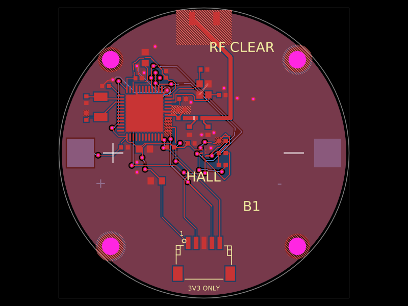
The PCB window is 34.6×40.6 mm, R2, for the fixed cable and two diagonal posts. PCB underside/top remain Z2.6/4.2 mm; carrier support Z17.3 mm, display front Z20.9 mm and bezel top Z22.3 mm. J4 remains at (0,+20.5) mm; disconnect its programming lead before closure. The USB keeps its rear position; the front switch has an 8×4 mm printed cap. The circular body remains Ø84.8 mm; the cap brings overall depth to 88.0 mm. No purchased part is rescaled.

The supplied display lead is shortened and soldered directly at J6 while retaining its original PH plug. Its unpublished wire dimensions remain accepted approximations: Ø1.2 mm rendered and Ø1.5 mm checked. Trial-dress the actual cable before cutting. No additional display connector or cable is purchased.

## Rebuild

With the pinned Bun dependencies and Python packages in [vendor provenance](vendor/README.md):

```sh
bun run build
python mechanical/generate.py
bun run cad:pcb
python mechanical/generate-assembly.py
bun run build
bun run check:assembly
python mechanical/render.py
```

`parameters.json` and the source scripts define all nominal geometry. Prints are restored from their recorded bed poses to assembled positions. `cad/assembled.glb`, `cad/exploded.glb` and the per-part OBJs use the same parts; OBJ is PCB-centred millimetres/+Z-up, glTF is metres/+Y-up. Relative model paths use included files.

Checks retain the complete rotor sweep, actual screen/package models, larger wire envelope, USB/button access and race-specific bearing interfaces. All six product meshes must be connected, watertight solids. Push-fit retention is a physical test; geometry checks cannot certify friction or printer capability. [Detailed limits](vendor/README.md), [fit budget](fit-budget.json), [geometry checks](geometry-check.json) and [bring-up](../validation/BRINGUP.md).
Related Packages
 More from this authorrushabhcodes/fidget-counter
 Discover something newDevesh36/orbit-turntableORBIT is a USB-C-powered display turntable for photographing jewellery, models and small products. Four-layer ESP32-C3 / ULN2003 PCB, geared stepper, OLED, push encoder, home switch and buzzer, with an enclosed and exploded assembly. Hardware prototype; firmware and physical qualification remain separate.