rushabhcodes/desk-fidget-counter
A desk knob assembly combining a circuit board with PETG-printed mechanical parts and vendor CAD-modeled hardware.
- Version
- 5.6.1
- License
- MIT
- Stars
- 0
ASSEMBLY.md
PCB

Schematic

# Assembly — E5 enclosure / E3 PCB

The product uses **six printed parts and four screws**: two DIN 965 M2×6 chassis screws and two M2×10 screws shared by the screen carrier and bezel. The complete 6712ZZ bearing is one purchased unit and one CAD object. The grip includes its optical track; there are no separate bearing clamps, lower retainer or skirt adhesive joint.

1. **Calibrate and print.** Start with the bearing-fit coupon and the actual 60×75×7 mm bearing. Use the supplied print orientations and [fit guide](mechanical/FIT.md). Print the six E5 product parts in PETG; test the integral grip/track for opacity at 950 nm. Deburr slots and fit surfaces without changing the optical track radius. The lid needs supports beneath its annular plate; keep supports off bearing mating surfaces.
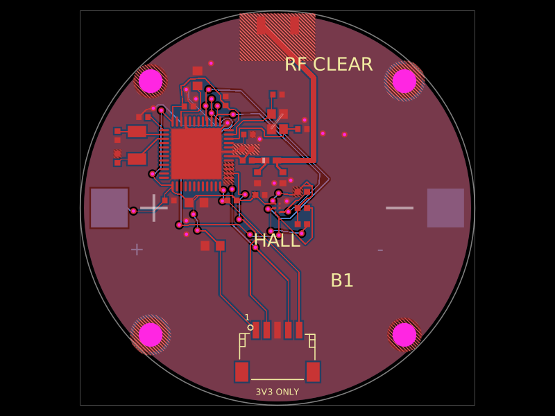
2. **Program and test the PCB before closure.** Connect the SWD service lead at J4, power the board over USB and flash the firmware. Then unplug power and the service lead. All 38 fitted components face upwards. J6 is unpopulated: use its labelled solder holes for the shortened cable supplied with Waveshare 19192. [Wiring and continuity checks](manufacturing/WIRING.md).
3. **Fit the PCB in the base.** Align rear USB-C with +Y and the front button with −Y, then seat the four locating holes on the pegs. The two screen-support posts pass through the routed window. Trim underside leads/joints to ≤0.8 mm and insulate the inspected solder wells with one layer of the specified polyimide tape. Keep the button actuator and USB mouth unobstructed.
4. **Close the chassis with two screws.** Attach six PORON pads to the lid using 0.05 mm 467MP: four Ø4 mm at (±30, ±15) mm and two Ø2.6 mm at (±6, −37) mm. Tap the pilot holes first. Drop `button-cap` into the open-top front guide with its small boss toward SW1, then install the lid with the two M2×6 screws. Check free motion, electrical closure before the stop and return to the released position. Do not preload the switch or use the shell to force a binding cap. J4's service lead must be removed before the bearing/rotor is fitted.
5. **Install bearing and grip with light hand pressure.** Seat the complete bearing in the grip pocket, then lower it onto the stationary post while guiding the integral optical track into the sensor's 3 mm fork. Use the calibrated push fits; stop if force is needed. Do not hammer or use the screws to force a bearing fit. Verify that the grip stays seated during normal handling and rotates freely through full turns. Physical pull-off retention and drag must be checked on the prototype.
6. **Fit the screen and its two shared screws.** Place `screen-carrier` on the two base posts. Orient the screen tab toward −X and fully seat its original display plug. Dress the eight wires inside the fixed window, clear of the rotating track. Install `screen-bezel`; its two M2×10 screws pass through the carrier into the base posts. Tighten gently until the plastic supports meet, keeping pressure off the glass. These two screws secure both carrier and bezel; no extra carrier screws are used.
7. **Bring up the complete device.** Recheck unobstructed rotation, wire clearance, USB insertion and button access. Initialize FRAM deliberately, verify clockwise/counter-clockwise counts and scrolling, and run the [first-build checks](validation/BRINGUP.md). Optional feet add 1 mm to the nominal 22.3 mm height.

The fixed screen, display cable and PCB do not rotate. The PCB has top-side assembly, a 34.6×40.6 mm window and accessible side ports. The body remains approximately Ø84.8×22.3 mm. No battery or toggle is fitted. The front cap adds 3.2 mm beyond the circular base; overall depth including it is 88.0 mm.

The screen uses the official Waveshare STEP without rescaling. The bearing's 60×75×7 mm envelope is published; its internal details and unpublished wire dimensions use the accepted approximations. CAD checks cover nominal geometry and the stated tolerance envelopes. Actual printed fit, retention, optical opacity and electronic operation still require prototype verification.
Related Packages
 More from this authorrushabhcodes/fidget-counter
 Discover something newDevesh36/orbit-turntableORBIT is a USB-C-powered display turntable for photographing jewellery, models and small products. Four-layer ESP32-C3 / ULN2003 PCB, geared stepper, OLED, push encoder, home switch and buzzer, with an enclosed and exploded assembly. Hardware prototype; firmware and physical qualification remain separate.