rushabhcodes/ESP32-E-Reader
Battery-powered ESP32-C3 e-reader board with USB-C LiPo charging/protection, buck-boost 3.3 V supply, Wi‑Fi MCU, e-paper and microSD interfaces, display charge-pump rails, and tactile power/navigation controls.
- Version
- 1.0.87
- License
- unset
- Stars
- 3
dist/assets/enclosure/stl/display-connection-check.json
{
  "nominal_installed_length_mm": 33.659926,
  "nominal_tail_length_mm": 33.66,
  "bend_radius_mm": 0.6,
  "modeled_contacts": 24,
  "contact_face": "bottom (-Z)",
  "route": {
    "type": "around_bottom_edge",
    "bendCenterY": -48.6,
    "panelPin1Verified": false
  },
  "connector_center_y_mm": -35.08101356236891,
  "solid_overlaps_mm3": {
    "Waveshare-3.97-G-nominal-outline": {},
    "EPD-flex-polyimide-nominal": {},
    "EPD-flex-tip-stiffener-nominal": {}
  },
  "connector_insulation_overlaps_mm3": {
    "EPD-flex-polyimide-nominal": 0.0,
    "EPD-flex-tip-stiffener-nominal": 0.0
  },
  "basis": "Waveshare Rev 1.0 mechanical drawing, printed page 4: 56.24 x 96.62 mm glass, 24 contacts at 0.5 mm, 12.50 mm tip, offset L-shaped tail with 33.66 mm projection, 3.00 mm stiffener and 1.70 mm contact exposure. The first bend begins at the marked 15.00 mm line (17.40 minus 2.40), beyond the PCB bottom edge; the bonded/driver region stays flat. Glass modeled at conservative 1.10 mm maximum table thickness. Undimensioned outline corners and 0.6 mm installation radius remain nominal. FH34SRJ is a short-contact, dual-contact candidate; its 0.30 +/-0.03 mm recommendation does not cover the panel full +/-0.05 mm thickness tolerance. Panel pin-1 direction is not established by the unlabeled mechanical drawing. CAD finger numbers follow the selected socket and must not be mistaken for verified panel numbering. Physical mating and bend radius require confirmation before PCB order.",
  "scope": "Nominal mesh clearance only. Run check-display-interface.py separately: CAD overlap success does not establish real panel-tail compatibility."
}
Related Packages
 More from this authorrushabhcodes/tetrisThis code defines various electronic component models—including a AAA battery holder, ATtiny85 microcontroller, switch, buzzer, display, and resistors—as hardware modules with detailed footprints, pin configurations, CAD models, and physical specifications for use in circuit design.
 Similar packagemohan-bee/esp32-c3This hardware design integrates an ESP32-C3 microcontroller, a USB-C connector, a power management IC (AP2112-3.3V regulator), a USB-to-Serial converter (CH340C), several resistors, capacitors, and user-accessible headers to facilitate USB communication, power regulation, and general I/O interfacing.
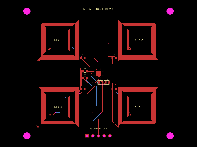 Discover something newhrithik18k/metal-touch-panelA PCB autorouting wrapper that corrects footprint-trace obstacle dimensions, solves routes with a preloaded trace-graph solver, and reports completed traces or routing errors.