rushabhcodes/ESP32-E-Reader
A compact ESP32-C3 e-reader PCB integrating LiPo charging/protection, USB-C, 3.3 V regulation, e-paper display bias generation, microSD storage, and tactile controls.
- Version
- 1.0.85
- License
- unset
- Stars
- 3
ORDERING.md
# PCB order gate — Waveshare 3.97inch (G)

**Do not submit this PCB candidate for assembly yet.** The revised nominal CAD
and print geometry are prepared, but the delivered panel tail has not been
qualified against the selected socket. An assembled unit has not been tested.

Buy the exact [Waveshare 3.97inch e-Paper (G), Robu SKU R254505](https://robu.in/product/waveshare-3-97inch-e-paper-display/):
800 × 480 landscape / 480 × 800 portrait, black/white/red/yellow, SSD2677.
This PCB accepts its raw panel, not the driver HAT. Keep the supplied HAT to
identify pin numbering and test the screen before disconnecting it, with power off.
Do not substitute a different 3.97-inch screen solely on size or resolution.

The candidate socket is [Hirose FH34SRJ-24S-0.5SH(50), LCSC C324726](https://www.lcsc.com/product-detail/C324726.html),
24 positions, 0.5 mm pitch, dual contact. Its exact supplier footprint and local
CAD replace FH12. It accepts a shorter exposed-contact pattern nominally,
but the panel and connector drawings have different tolerance recommendations.

Before ordering the PCB, resolve these facts on the exact panel revision:

1. Establish which physical finger is panel pin 1. The Waveshare mechanical
   drawing labels a **white oil line**, not pin 1. The HAT drawing labels its
   connector pins, but does not alone prove the unfolded tail orientation.
   Our canonical socket pin 1 is +X; a wrong mapping places boost rails on
   the wrong panel pins. Do not power the candidate connection to find out.
2. Confirm full insertion and latch closure in C324726, without forcing it,
   and obtain supplier acceptance or verify the actual thickness and contact
   overlap. Panel reinforced thickness is 0.30 ± 0.05 mm; Hirose recommends
   0.30 ± 0.03 mm. Contact exposure and stiffener recommendations also differ; the panel
   finger width is undimensioned and our 0.35 mm CAD fingers are illustrative.
   Verify real contact overlap; matching nominal pitch is insufficient.
3. Confirm the actual tail can follow the edge wrap with its first 15.00 mm
   flat and bends only at permitted zones. The OEM marks the first line;
   it does not rate the modeled 0.6 mm installed radius. Check the nominal
   33.66 mm projection, full seating, slack and freedom from tension while
   closing the two case halves and actuating every button.

The [interface report](assets/enclosure/stl/display-interface-check.json) keeps
this order gate explicit. `python3 scripts/check-display-interface.py` exits
nonzero while supplier/sample evidence is missing. `bun run export:gerbers`
also runs that gate before producing ordering files. The [CAD fit report](assets/enclosure/stl/display-connection-check.json)
and [reference slice](assets/enclosure/stl/printability-check.json) prove only
the modeled assembly and reference toolpath generation, within their scopes.

Digital verification completed for this local revision:

- Final build: zero errors, 224 routed traces and 207 ordinary through vias.
- Gerber-derived shorts: none on top, bottom, inner1 or inner2.
- All four screw-hole copper keepouts pass; the candidate BOM and placement export
  contains 87 matching rows with supplier IDs.
- Native 3D assembly: 98 models, none missing; no case/component collisions.
  Screen, PCB, battery and cover installation paths and all four key strokes pass
  the nominal CAD checks.
- Two connected, manifold printed shells; the reference 0.4 mm nozzle / 0.2 mm
  slice and inspected toolpaths pass. The plate estimate is 34.28 g including
  supports, about 4 h 7 min. Use the printing guide for the target-printer setup.

These results do not qualify the delivered panel tail. The fabrication archive
under `dist/CANDIDATE-NOT-FOR-ORDER-gerbers.zip` is for review only; it must not
be uploaded for a PCB order until the physical interface is qualified.

Rev. H keeps two printed parts, snap closure and the 16.8 mm device thickness.
It removes the PCB slot, routes outside the bottom edge, puts the four complete keys at X ±16.5 and ±27.5 mm beside a protected
central ribbon channel; no moving flange crosses the front tail.
The lower mounts are at (−25.5, −36.5) and (+28, −29) mm; R6 moves to Y −22 mm
and the lowest screen clips move to Y −22 mm to clear the right mount.
Print the two matched shells at 100% scale
using [the printing guide](assets/enclosure/PRINTING.md).

After the tail is qualified, repeat PCB netlist/placement/build, shorts on all
four layers, assembly-export guard, CAD clearance and print checks. Use the
resulting **current** fabrication files. The public 1.0.76 release predates
these screen and enclosure changes and must not be used for this panel order.

The repository contains hardware and enclosure sources, not reader firmware.
A working device also requires the specified battery, antenna, microSD, four
internal PCB screws and cushioning/adhesive supplies listed in the README.

Battery: **SparkFun PRT-13855**, protected 1S LiPo, 3.7 V nominal / 4.2 V
charge voltage, 2000 mAh, 49.2 × 68.8 × 5.6 mm. The assembly now shows its
pouch, red/black leads and a mating JST-PH 2-pin plug. Red must reach
**BT1 pin 1 (BATT_P)**, black **BT1 pin 2 (BATT_N_RAW)**. The black wire
is the protected battery return, not a direct bypass to system ground.
The nominal harness route requires **94 mm usable free leads**, including
installation slack. Verify this, plug polarity, the allowed charge current
(board nominal 356 mA), dimensions and swelling clearance on the actual pack.
Our model does not certify an unmeasured supplier cable.

[SparkFun](https://www.sparkfun.com/lithium-ion-battery-2ah.html) currently
excludes international battery shipping; the exact-part
[LionCircuits India listing](https://www.lioncircuits.com/parts/PRT-13855)
currently says out of stock (12 October 2026). Resolve sourcing before placing
the hardware order. Do not substitute a pack solely by capacity or plug size.

Stock replacements: J1 is now [C165948, HRO TYPE-C-31-M-12](https://jlcpcb.com/partdetail/C165948),
and U1 is [C15220, TI BQ24073RGTR](https://jlcpcb.com/partdetail/C15220).
Their footprint/pin mapping and charger TD grounding are updated in the source.
Confirm live assembly inventory in JLCPCB when ordering; the recent published
stock figures are cached and do not reserve parts. The display qualification
gate above still applies.
Related Packages
 More from this authorrushabhcodes/tetrisThis code defines various electronic component models—including a AAA battery holder, ATtiny85 microcontroller, switch, buzzer, display, and resistors—as hardware modules with detailed footprints, pin configurations, CAD models, and physical specifications for use in circuit design.
 Similar packagemohan-bee/esp32-c3This hardware design integrates an ESP32-C3 microcontroller, a USB-C connector, a power management IC (AP2112-3.3V regulator), a USB-to-Serial converter (CH340C), several resistors, capacitors, and user-accessible headers to facilitate USB communication, power regulation, and general I/O interfacing.
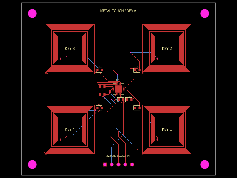 Discover something newhrithik18k/metal-touch-panelA PCB autorouting wrapper that corrects footprint-trace obstacle dimensions, solves routes with a preloaded trace-graph solver, and reports completed traces or routing errors.