runpatrick/sa-sim-pcb
This code defines PCB footprints for various electronic modules, including BG95 cellular modem, BNO086 sensor, BQ25180 battery charger, and BQ27220 power management IC, detailing their physical pad layouts and key external features.
- Version
- 1.0.6
- License
- unset
- Stars
- 0
footprints/nrf52840.tsx
// nRF52840 QFN73 7×7mm 0.5mm pitch — 72 perimeter pads + 1 center thermal EP
// Pin 1 = bottom-left corner, CCW numbering (IPC convention)
// Side distribution: 20-bottom, 16-right, 20-top, 16-left = 72 + EP(73)
// Pad lengths: 0.4mm (perpendicular to edge) × 0.25mm (along edge)

export const nrf52840Footprint = () => (
  <footprint>
    {/* BOTTOM row pins 1-20 (left → right), y = +3.7mm (south edge) */}
    {Array.from({ length: 20 }, (_, i) => (
      <smtpad
        portHints={[String(i + 1)]}
        shape="rect"
        width="0.25mm"
        height="0.4mm"
        pcbX={`${-4.75 + i * 0.5}mm`}
        pcbY="3.7mm"
        layer="top"
      />
    ))}

    {/* RIGHT column pins 21-36 (bottom → top), x = +3.7mm */}
    {Array.from({ length: 16 }, (_, i) => (
      <smtpad
        portHints={[String(i + 21)]}
        shape="rect"
        width="0.4mm"
        height="0.25mm"
        pcbX="3.7mm"
        pcbY={`${3.25 - i * 0.5}mm`}
        layer="top"
      />
    ))}

    {/* TOP row pins 37-56 (right → left), y = -3.7mm (north edge) */}
    {Array.from({ length: 20 }, (_, i) => (
      <smtpad
        portHints={[String(i + 37)]}
        shape="rect"
        width="0.25mm"
        height="0.4mm"
        pcbX={`${4.75 - i * 0.5}mm`}
        pcbY="-3.7mm"
        layer="top"
      />
    ))}

    {/* LEFT column pins 57-72 (top → bottom), x = -3.7mm */}
    {Array.from({ length: 16 }, (_, i) => (
      <smtpad
        portHints={[String(i + 57)]}
        shape="rect"
        width="0.4mm"
        height="0.25mm"
        pcbX="-3.7mm"
        pcbY={`${-4.25 + i * 0.5}mm`}
        layer="top"
      />
    ))}

    {/* Center thermal EP (pin 73) — GND */}
    <smtpad
      portHints={["73"]}
      shape="rect"
      width="5.4mm"
      height="5.4mm"
      pcbX="0mm"
      pcbY="0mm"
      layer="top"
    />

    {/* Body silkscreen */}
    <silkscreenpath
      route={[
        { x: -3.5, y: 4.0 },
        { x: 3.5, y: 4.0 },
        { x: 3.5, y: -4.0 },
        { x: -3.5, y: -4.0 },
        { x: -3.5, y: 4.0 },
      ]}
    />
  </footprint>
)
Related Packages
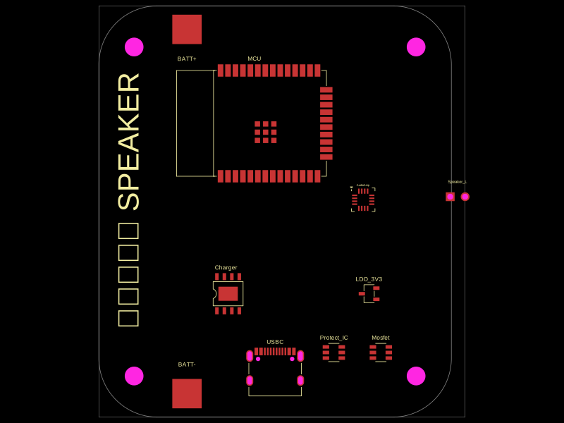 Similar packagemohan-bee/speakerThis code defines configurable 3D models and PCB footprints for various electronic components, including a battery charger IC, a dual Hall sensor, a dual power switch, and a voltage regulator, with detailed pinouts, footprints, and CAD models for schematic and physical design.
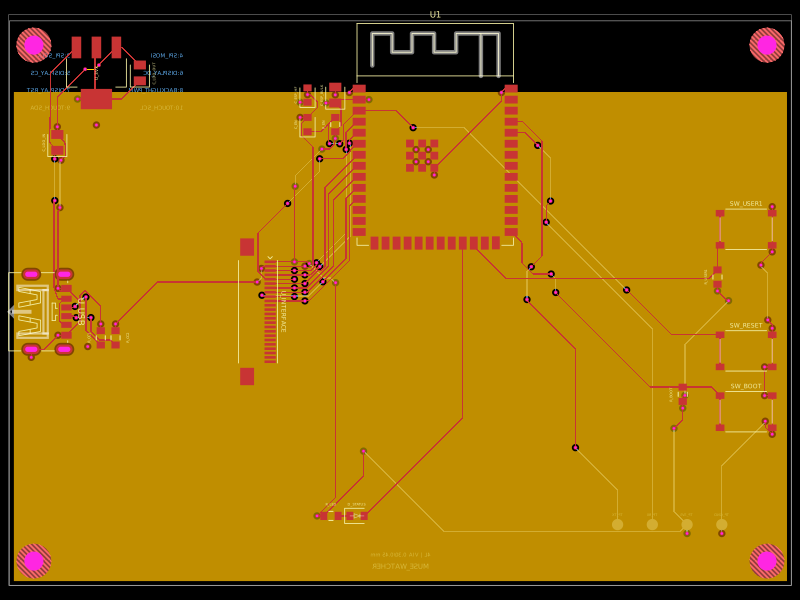 Discover something newShiboSoftwareDev/muse-sensecap-watcher-replacementA 4-layer ESP32-S3 carrier board with USB-C power, AMS1117 3.3V regulation, reset/boot/user buttons, status LED, capacitors/resistors, and a 24-pin FFC interface.