runpatrick/sa-sim-pcb
This code defines PCB footprints for various electronic modules, including BG95 cellular modem, BNO086 sensor, BQ25180 battery charger, and BQ27220 power management IC, detailing their physical pad layouts and key external features.
- Version
- 1.0.6
- License
- unset
- Stars
- 0
footprints/jstph2.tsx
// JST PH 2-pin top-entry connector (S2B-PH-K-S, through-hole)
// 2.0mm pitch between pins; 0.95mm hole / 1.55mm pad
// Pin 1 = positive (BAT_P), pin 2 = negative (GND) per JST polarity convention

export const jstph2Footprint = () => (
  <footprint insertionDirection="from_above">
    <platedhole
      portHints={["1"]}
      pcbX="-1.0mm"
      pcbY="0mm"
      outerDiameter="1.55mm"
      holeDiameter="0.95mm"
      shape="circle"
    />
    <platedhole
      portHints={["2"]}
      pcbX="1.0mm"
      pcbY="0mm"
      outerDiameter="1.55mm"
      holeDiameter="0.95mm"
      shape="circle"
    />
    <silkscreenpath
      route={[
        { x: -2.5, y: -2.0 },
        { x: 2.5, y: -2.0 },
        { x: 2.5, y: 2.0 },
        { x: -2.5, y: 2.0 },
        { x: -2.5, y: -2.0 },
      ]}
    />
  </footprint>
)
Related Packages
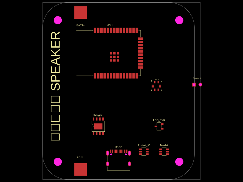 Similar packagemohan-bee/speakerThis code defines configurable 3D models and PCB footprints for various electronic components, including a battery charger IC, a dual Hall sensor, a dual power switch, and a voltage regulator, with detailed pinouts, footprints, and CAD models for schematic and physical design.
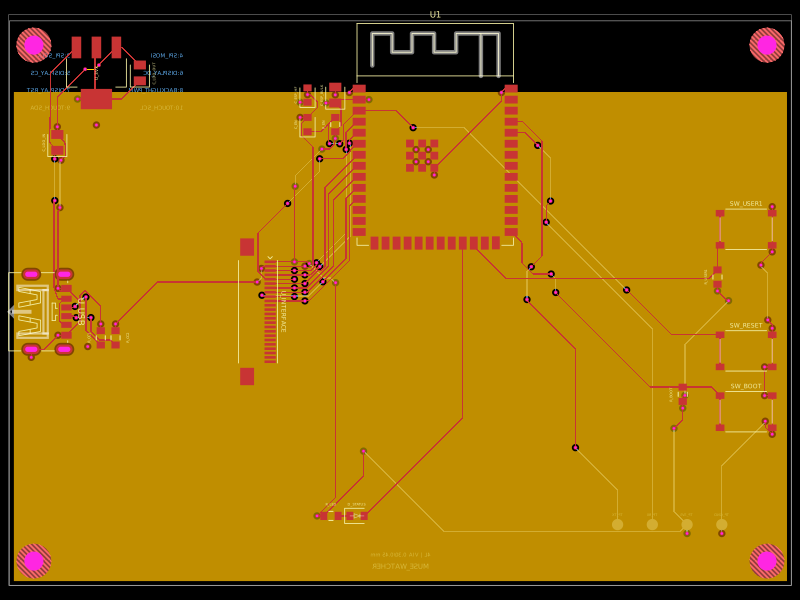 Discover something newShiboSoftwareDev/muse-sensecap-watcher-replacementA 4-layer ESP32-S3 carrier board with USB-C power, AMS1117 3.3V regulation, reset/boot/user buttons, status LED, capacitors/resistors, and a 24-pin FFC interface.