pixalynx/pixal-nfc-card
This code defines React components representing specific electronic hardware components—namely, a 100-ohm SMD resistor, a surface-mount LED, and a chip with labeled pins—each modeled with detailed footprints, 3D CAD models, and manufacturer part information for PCB design.
- Version
- 1.1.0
- License
- unset
- Stars
- 0
fabrication/rev-b/REV-B-REVIEW.md
PCB

Schematic

# Revision B independent engineering re-review

Date: 2026-09-17. Scope: revised source, generated Circuit JSON, netlist, real exported Gerbers/drill, BOM/CPL, stencil, PCB/schematic previews, antenna geometry, assembly and mechanical specifications. This is a desktop engineering review, not measured hardware qualification or supplier CAM approval. Evidence and source hashes accompany the release bundle.

**Verdict: technically credible prototype design, ready to submit for supplier CAM review. Not yet cleared for an unconditional JLCPCB assembly order or production.** No confirmed schematic/pin-map/copper short/open defect remains in the reviewed outputs. Exact-part sourcing and approval of small lands, thin-board assembly and the proposed panel remain outstanding. Resonance/read range and the protective card construction require samples.

## What changed

| Previous issue | Revision B action | Status |
|---|---|---|
| H1 RF loading and reverse stress from LED branch | Removed R1 and D1, their pads and LED net; direct AC0/AC1 feeds | Closed in design |
| H2 undersized U1 paste | Explicit 1:1 paste; specified 0.10 mm foil; independently verified all 5 exported apertures | Artwork fixed; factory process acceptance pending |
| H3 antenna holes receive paste / small rings | Ø0.80/0.30 mm lands/drills; 0.25 mm rings; checked removal of four auto-generated paste circles | Closed in canonical export |
| H4 false L1 CPL placement | Explicit one-part BOM/CPL with set equality checks; L1 is printed copper | Closed in canonical export |
| H5 0.6 mm assembly handling / panel | Standard PCBA specification; dimensioned 2-up carrier, fiducials/tooling/tab proposal | Supplier panel CAM and process acceptance pending |
| H6 unverified supply | Exact MPN and part ID retained; checked stock; explicit procurement gate | Open: LCSC out of stock; JLC assembly quantity not established |
| M1 unmeasured RF | NFC-only baseline; quantified estimate/tolerance; RF/phone test plan and pass criteria | Plan complete; measurements pending |
| M2 wrong Gerber text anchoring | Centre anchors, repositioned text, readable font sizes; inspected actual Gerbers | Closed |
| M3 no enforceable RF exclusion | Both-layer keepout with L1 exception; independent population/copper equivalence audit | Closed for reviewed artifact |
| M4 unknown finished thickness | 1.60 mm proposed maximum envelope and protected IC zone; defined handling screens | Specification complete; material/process validation pending |
| M5 incorrect LED documentation | README corrected; removed LED from actual design | Closed |
| M6 ambiguous BOM / ordering spec | MPN, supplier, package, count, finish, stencil and placement orientation instructions | Closed |
| Small silk / schematic padding / reproducibility | ≥0.15 mm silk strokes, smaller schematic box and explicit sheet, pinned dependencies, release regression checks | Closed except advisory schematic routing suggestions |

Previous report correction: the default paste width and height were each 70% of copper, giving 49% of pad area (51% area reduction), not a 70% area reduction.

## Electrical and RF review

U1 remains ST25TN01K-AFH5, a passive NFC Type 2 tag. Inner L1 terminal → top ANT_A feed → pin 3 AC0. Outer L1 terminal → top ANT_B feed → pin 4 AC1. The bottom winding closes the DC path between terminals; that DC continuity is intentional. Pins 1 NC3, 2 NC1 and 5 NC2 are isolated copper lands with solder for package retention. Neither the central land nor the antenna is ground. No supply, decoupling or pull resistors are required for this two-terminal passive configuration. The netlist confirms only these two connections and three NCs.

U1 footprint is the manufacturer land arrangement, expressed in exact metric dimensions after removing submicrometre import rounding: four 0.20 × 0.60 mm pads at local x=±0.40, y=±0.50, plus one central 0.20 × 1.60 mm pad. Rotation 180° puts AC pins on the left. The release checks verify all five physical pin coordinates. Supplier CPL-library rotation still needs a visual pin-1 check against the assembly specification.

The coil is 5 turns on bottom copper, 0.45 mm wide with 0.45 mm gaps; outer centreline rectangle 46 × 44 mm. Winding copper occupies 46.45 × 44.45 mm, with the enlarged outer terminal extending the total bottom-copper width to 46.625 mm. Twenty-one winding segments total 829.5 mm, before feeds. There are two interlayer terminal holes and no ground plane, additional vias or unrelated copper in the RF region. The inner feed crosses winding turns on the opposite layer as intended.

Independent geometry gives 3.275 mm coil clearance to the actual rounded outline, not just its bounding box. Terminal-to-adjacent-turn copper gap is 0.275 mm. Estimated winding inductance is 2.536 µH (a square current-sheet approximation independently gives ~2.536 µH); estimated winding DC resistance at 35 µm copper is 0.908 Ω. These are not RF loss/Q measurements and exclude feed/stack parasitics.

With the IC's 47.5–52.5 pF range, the idealized resonance is 14.50–13.79 MHz (14.13 MHz nominal). ST AN2866 recommends 13.6–14.0 MHz for ST25TN short-range optimization and requires final-material effects to be considered. The geometry is credible but cannot guarantee tuning. There is no external matching network; the internal capacitor is the intended baseline. No blind shunt capacitor has been added. See RF-VALIDATION.md for the measurement and adjustment process. [ST AN2866](https://www.st.com/resource/en/application_note/an2866-how-to-design-a-1356-mhz-customized-antenna-for-st25-nfc--rfid-tags-stmicroelectronics.pdf), [ST datasheet](https://www.st.com/resource/en/datasheet/st25tn01k.pdf).

## CRITICAL

No confirmed critical electrical, pin-mapping, routing or export defect found in revision B. This statement is limited to the checks below; it does not certify RF functionality of unbuilt hardware.

## HIGH

### H-B1 — Exact IC supply remains unresolved

- **Where/finding:** U1, ST25TN01K-AFH5 / C3303589; LCSC showed Out of Stock on the review date. JLC lists an Extended Part, but usable assembly inventory has not been established.
- **Why:** a technically correct BOM can still prevent assembly.
- **Required implementation/change:** secure the exact MPN through JLC stock/preorder or accepted consignment before committing to assembly. Retain the reviewed package/pinout; any substitution requires a new electrical/footprint review. The release specification now makes this explicit. [LCSC stock](https://www.lcsc.com/product-detail/C3303589.html), [JLC part listing](https://jlcpcb.com/partdetail/STMicroelectronics-ST25TN01KAFH5/C3303589).

### H-B2 — Supplier process acceptance remains required

- **Where/finding:** U1 0.20 mm-wide manufacturer lands are below generic JLC 0.25 × 0.25 mm SMD-pad guidance; the retained 0.6 mm card also falls below Economic PCBA thickness support. Standard requires rails/fiducials; the final panel has not been generated or approved by JLC.
- **Why:** generic DRC cannot assure small-pad stencil yield or thin-board handling/placement accuracy.
- **Required implementation/change:** obtain CAM acceptance of land/mask geometry, 0.10 mm foil and supplied apertures; have JLC finalize the 99.6 × 124 mm 2-up panel, tooling and depanelization, then verify U1 pin 1 in its placement preview. Do not inflate manufacturer pads without a redesign. Stencil artwork, panel drawing and physical orientation instructions are supplied, but approval is not claimed. [JLC PCB capabilities](https://jlcpcb.com/capabilities/pcb-capabilities), [assembly capabilities](https://jlcpcb.com/capabilities/pcb-assembly-capabilities).

## MEDIUM

### M-B1 — RF performance remains unmeasured

- **Where/finding:** complete antenna/IC/final-cover system. No physical prototype data exist.
- **Why:** parasitics, IC loading, final material and phones determine the useful response; calculation is insufficient.
- **Required change:** execute RF-VALIDATION.md on a small lot, tune geometry from measured results, and repeat required phone tests. This is a production gate, not a reason to prohibit controlled prototype fabrication after CAM acceptance.

### M-B2 — Finished-card mechanical qualification remains open

- **Where/finding:** U1 protection and final nonmetallic covering; nominal assembled local thickness ~1.15 mm before solder/protection. The 1.60 mm maximum proposed stack is a budget, not an already-built enclosure.
- **Why:** exposed package stress or wallet bending can break joints or winding copper; this is thicker than a standard 0.76 mm card.
- **Required change:** select/validate the cover or encapsulant within MECHANICAL.md's budget and run handling tests with RF retest. No conductive backing over the antenna. Do not market the rigid FR-4 as a qualified flexible card.

## LOW

The schematic checker offers two mutually competing optional moves of U1 to straighten opposite leads. The coil and IC have different symbol pin spans, so both cannot be achieved by translating U1 alone. The rendered schematic is readable, labels do not obscure connections, and the explicit NC markings are correct. This is an aesthetic advisory with no fabrication effect; pin-padding warnings were fixed. A symbol redesign can remove the advisory in future without changing copper.

The ordinary development export still contains upstream paste/CPL defects. The canonical `bun run fab` path checks and corrects them without patching dependencies. Using raw `tsci export` would reintroduce manufacturing errors; README and STATUS.txt identify the only approved candidate workflow.

## Verification and diagnostic dispositions

- TypeScript, tscircuit build, netlist and placement checks pass. One board entrypoint is explicitly configured so generated Circuit JSON cannot accidentally become another build target.
- Only build warnings: U1 has no requires_power and no requires_ground pins. Both are appropriate for the passive RF-powered IC and narrowly allowlisted in the release normalizer. Any additional warning or circuit error aborts export.
- Bitmap short detection reports exactly two bottom-layer junctions near (2.2,3) and (6.7,-3), identifying the L1 plated holes against the L1 coil trace. These are expected physical connections represented by different primitive ownership. Release checks their count, coordinates and participants; independent segment, endpoint, copper-equivalence and connectivity checks confirm no adjacent-turn bridge. This is not a blanket short waiver.
- All five U1 copper/paste lands match expected geometry; top paste area ratios at 0.10 mm foil are 0.75 (outer pads) and 0.889 (centre), with width/foil ratio 2.0. No antenna paste remains. Exported mask exposes only five IC pads and the two terminals; bottom mask exposes just the two terminals.
- Actual Gerber copper and source copper have <0.001 mm² symmetric-difference tolerance (measured effectively zero). Bottom is one continuous winding island; top is two separate feeds plus three isolated NC pads. No copper fill or extra vias.
- Minimum unrelated copper clearance: 0.175 mm. Minimum turn gap: 0.45 mm. Minimum terminal-to-other-turn gap: 0.275 mm. Annular rings: 0.25 mm. Two Ø0.30 mm plated drill positions verified.
- Minimum silk stroke 0.15 mm; minimum silk-to-mask-opening clearance 0.45 mm; silk and copper lie inside routed-edge limits. Actual Gerber views inspected at board and U1 detail scales. Text alignment is fixed in output, although preview and Gerber fonts remain visually different.
- BOM and CPL contain exactly U1; checked position (13.5,0), top, 180°. Exact MPN, supplier ID, package and quantity are explicit.
- Regression checks reject reduced paste, DNP U1, unknown paste, an adjacent-turn short and rogue copper inside the coil.
- The Gerber parser intentionally supports this export's metric 4.6-coordinate C/R-aperture linear/flash subset, not arbitrary Gerber syntax. Future exporter/geometry changes need reviewer attention. Geometry audits do not simulate magnetic coupling or solder process yield.

## Fabrication Readiness Summary

| Question | Answer |
|---|---|
| Is the schematic electrically sound? | Yes by pin/net review: passive IC directly across coil, NCs isolated, LED load removed. Hardware behavior still requires prototype testing. |
| Is the NFC antenna design credible? | Yes as an initial 5-turn ~2.54 µH design; resonance/Q/range are unmeasured. |
| Is the matching network credible? | Yes: direct coil plus internal 50 pF is appropriate; no invented generic filter network. Final tuning remains empirical. |
| Is the PCB layout appropriate for NFC? | Yes within this review: copper exclusion, wide/gapped loop, short differential feeds, no ground/metal plane. |
| Are there likely footprint/pin-mapping problems? | None found. Manufacturer lands and physical pin coordinates agree; factory library orientation still needs confirmation. |
| Is the BOM suitable for JLCPCB assembly? | Structurally yes and explicitly specified; sourcing and Standard-PCBA/CAM acceptance remain unresolved. |
| Is the board safe to send to fabrication? | Ready to send for CAM review. Order a small prototype lot only after H-B1/H-B2 close. Not production-qualified. Bare-board prototypes still need small-land CAM acceptance, but do not depend on IC stock if ordered unassembled. |

## Changes Required Before Fabrication

1. Secure ST25TN01K-AFH5 supply for any assembled order.
2. Get supplier approval for U1 lands/mask and the supplied stencil geometry/foil.
3. Finalize Standard-PCBA panel, rails/fiducials/tooling and thin-board handling; verify physical U1 pin-1 orientation and board-centred coordinate translation in supplier CAM.
4. Use only the checked single-unit Gerbers and matching BOM/CPL from the canonical release bundle; obtain supplier CAM previews before production starts.
5. Build the controlled prototype lot. Complete RF, phone/NDEF and mechanical validation before any production quantity; revise geometry if the measurements require it.

No order, payment, supplier message, stock reservation or physical measurement was performed during this task.
Related Packages
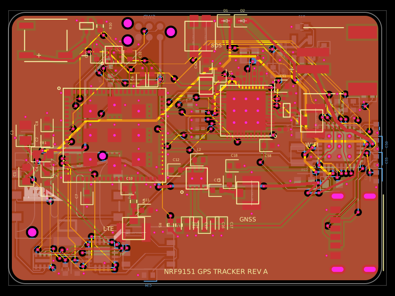 More from this authorpixalynx/nrf9151-gps-trackerA compact 44×32 mm, 4-layer nRF9151 LTE-M/NB-IoT/GNSS tracker PCB with nPM1300 LiPo/USB-C power, nano-SIM/eSIM switching, nRF7002 Wi‑Fi scanning, accelerometer, antennas, buzzer, LEDs, SOS button, and SWD/debug connectors.
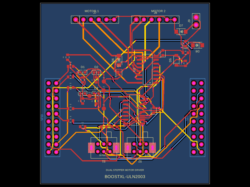 Similar packageabse/boostxl-uln2003This code defines a React component that models a through-hole or surface-mount LED with specified pin labels, footprint, silkscreen, and 3D CAD model for PCB layout.
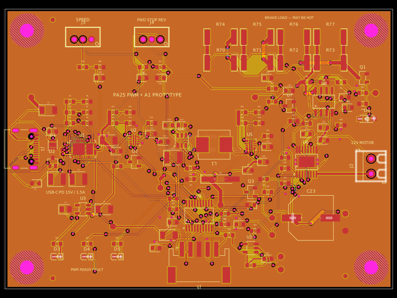 Discover something newAnasSarkiz/usb-c-pwm-pa25A component library defining an AO3400A N-channel MOSFET, 47 µF polarized capacitor, 3-pin through-hole connector, and 9.1 V Zener diode with PCB footprints and 3D CAD models.